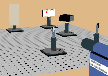
Online physics courses need online laboratories. Here we are developing tools for optics laboratories. Students will be able to move components on an optical breadboard, align the components, trace a He-Ne laser beam through the system and make measurement. The app is under development and you can explore the first steps.
You are presented with a He-Ne laser, an optical breadboard and several optical components. The components can be dragged to different positions on the breadboard and the components can snap to the holes on the breadboard which have a spacing of 1 unit = 2.5 cm. The screen is 4 units wide and 2 units high and the lines on the screen are spaced by ½ unit. Clicking anywhere on the breadboard you can rotate and zoom the view. Currently, you can steer the laser beam onto a target in three dimensions using two mirrors. A transparent viewer can help you align the beam. All components can be translated and rotated, post holders can be raised and lowered, and mirrors can be tilted up and down with the mouse. (Touch has not yet been enabled.) You can measure the index of refraction of a glass block with dimensions of 2.8 by 2.8 by 1.4 units.
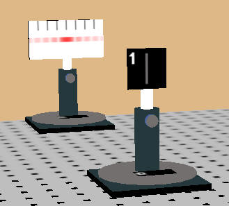
A He-Ne laser beam (λ = 633 nm) produces Fraunhofer diffraction and
interference pattern that you can observe on a screen. You can drag four
different slides into the the of the laser beam, and you can vary the slide to
screen distance. Clicking anywhere on the breadboard you can rotate and
zoom the view. The screen and the slides snap to the holes on the
breadboard which have a spacing of 1 unit = 2.5 cm. The screen is 4 units
wide and 2 units high and the lines on the screen are spaced by ½ unit.
Three of the slides block all the light except for a
single w = 20 μm wide slit, or two or four w = 20 μm wide slits with slit
spacing d. From the observed patterns you can verify the slit width w and
determine the slit spacing d. The only thing blocking the laser light on a
fourth slide is a hair. You can measure the width of the hair using the
diffraction pattern produced by the laser light.
The lines on the slides are not drawn to scale. Their purpose is just to identify the slides. The most intense regions of the diffraction and interference patterns always have the same maximum color intensity allowed by the computer graphics. A realistic decrease in the color intensity with distance from the slit(s) would make the dimmer regions of the diffraction and interference patterns invisible at larger distances. That is a limitation of the computer graphics.
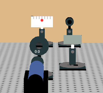
The He-Ne laser beam (λ = 633 nm) is unpolarized. You have 3 (ideal) linear polarizers and a power meter with a Bluetooth connection to a digital readout to monitor the beam intensity. You can also monitor the intensity of the laser beam on a screen (corrected for the average response of the human eye to light). The polarizers are mounted in a rotation stage. The transmission axis of the polarizers is horizontal when the rotation stage reads zero. You can explore what happens to the transmitted intensity if you rotate a third polarizer between two crossed polarizers and you can verify the Law of Malus. You can also reflect the laser beam off a glass slide and explore polarization by reflection. The back of the glass slide is painted black to absorb the transmitted portion of the beam. The slide is made of high-index of refraction glass, you can measure the index of refraction by finding the the Brewster angle.
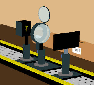
Determine the effective focal length of a bi-convex and two plano-convex lenses. The object is a beam (representing a point source at infinity). You can vary the aperture size by varying the beam radius. Use the mouse to move the lens and the screen along an optical rail and to zoom and rotate the view. The major unit of the scale on the track is cm. For large apertures, look for spherical aberrations and observe coma and astigmatism as you rotate the lens. For some lenses coma is the dominant aberration, while for others it is astigmatism.
Exact ray tracing equations for thick lenses are used. (Reference: Learn Optics)
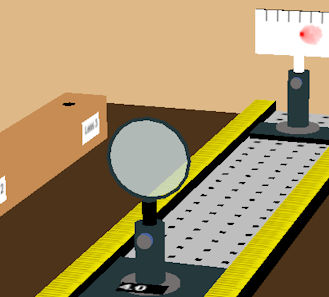
Determine the effective focal length of a bi-convex and two plano-convex lenses. The object is a lamp with markings. Use the mouse to move the lamp, lens, and the screen along an optical rail and to zoom and rotate the view. The major unit of the scale on the track is cm. For large apertures, look for spherical aberrations and observe coma and astigmatism as you rotate the lens.
Exact ray tracing equations for thick lenses are used. (Reference: Learn Optics)
Suggestions for improvements are welcome.
Code is on Github.