Simple DC circuits and Resistance Measurements
In this lab you will you will use an on-line simulation from the University of
Colorado PhET group to explore simple DC circuits and you will determine the resistance of different resistors by
- reading the code printed onto some of the resistors,
- measuring the resistance using a Wheatstone bridge (simulation),
- calculating the resistance using given properties of the material the
resistor is made of.
Open a Microsoft Word document and keep a log of your
activities. Answer all the questions in blue font.
Part 1, DC circuits
Link to the simulation:
https://phet.colorado.edu/en/simulations/circuit-construction-kit-dc
Click the Lab icon. Explore the interface!
- Components are dragged from the toolbox to make circuits.
- To explore the properties of a component, tap it. You can then
change many properties and also remove the component.
 (a) Use one ideal battery (24 V, 0 Ω internal
resistance), a light bulb (20 Ω) resistance) and ideal wires (near 0
Ω resistance) to build the circuit shown on the right. Make sure your
light bulb lights up. Use the voltmeter to measure the potential difference (ΔV)
across the battery. Record only the magnitude of the potential
difference (omit +/- signs). Make a similar potential difference
measurement across the bulb and across each length of wire. With
the noncontact ammeter, measure the current through the bulb, IBulb.
(a) Use one ideal battery (24 V, 0 Ω internal
resistance), a light bulb (20 Ω) resistance) and ideal wires (near 0
Ω resistance) to build the circuit shown on the right. Make sure your
light bulb lights up. Use the voltmeter to measure the potential difference (ΔV)
across the battery. Record only the magnitude of the potential
difference (omit +/- signs). Make a similar potential difference
measurement across the bulb and across each length of wire. With
the noncontact ammeter, measure the current through the bulb, IBulb.
Fill in "Table A" below..
| ΔVBattery |
ΔVwire A |
ΔVwire B |
ΔVBulb |
IBulb |
| |
|
|
|
|
Now use two ideal batteries (24 V, 0 Ω internal resistance), three light bulb
(20 Ω) resistance) and as many ideal wires as needed to build several different
circuits.
(b) Use all the components (two batteries, 3 light bulbs) and connect them
in such to produce the most light. (The largest possible current should
flow through the bulbs. You can connect the batteries and bulbs in series
or in parallel as needed.)
Make measurements and fill in "Table B" below.
| ΔVBattery |
IBattery |
ΔVany Bulb |
Iany Bulb |
| |
|
|
|
(c) Use all the components (two batteries, 3 light bulbs) and connect them
in such to produce the least amount of light or current, but not zero light or
current. (The smallest possible non-zero current should flow through the
bulbs.)
Make measurements and fill "Table C" below.
| ΔVBattery |
IBattery |
ΔVany Bulb |
Iany Bulb |
| |
|
|
|
Set up the circuit shown on the right with three
10 Ω bulbs and one 9 V battery.
(d) Observe the brightness of the bulbs.
Make measurements and fill in "Table D" below.
| ΔVBattery |
IBattery |
ΔVBulb 1 |
IBulb 1 |
ΔVBulb 2 |
IBulb 2 |
ΔVBulb 3 |
IBulb 3 |
| |
|
|
|
|
|
|
|
(e) Change the internal resistance of the battery to 1 Ω. What
happens?
Make measurements and fill in "Table E" below.
| ΔVBattery |
IBattery |
ΔVBulb 1 |
IBulb 1 |
ΔVBulb 2 |
IBulb 2 |
ΔVBulb 3 |
IBulb 3 |
| |
|
|
|
|
|
|
|
Paste Tables A - E into your log and comment on your measurements.
Part 2, Resistance Measurements
Background:
 Any device that offers resistance to current flow has an equivalent
resistance. If a voltmeter is used to determine the voltage V across the
device and at the same time an ammeter is used to measure the current I flowing
through the device, then this resistance can be found by dividing V by I, i.e.
R = V/I.
Any device that offers resistance to current flow has an equivalent
resistance. If a voltmeter is used to determine the voltage V across the
device and at the same time an ammeter is used to measure the current I flowing
through the device, then this resistance can be found by dividing V by I, i.e.
R = V/I.
The resistance of the device can also be determined with an ohmmeter. A
simple ohmmeter is a voltage source V in series with an ammeter. The
component, whose resistance is to be measured, is disconnected from any
circuit and the ohmmeter is connected across it. The equivalent resistance
is R = V/I, where I is the current flowing through the ammeter. The
resistance of the component is R minus the (usually very small) resistance of
the ohmmeter itself.
The accuracy of an ohmmeter is limited by its internal
resistance. When extremely accurate measurements are needed, a
Wheatstone bridge is used. A diagram of a Wheatstone bridge is shown on
the right. A Wheatstone bridge uses four resistances. R2 is
precisely known, it is the reference or standard resistance. The
ratio R3/R4 can be adjusted, but its value is
always known. The diagram shows a single coil that is divided by the
tap B. The ratio of the resistances R3 and R4
equals the ratio of the corresponding lengths of coil. This device is
called a potentiometer. Rx is
the resistance to be determined. A power supply with a switch is
connected across points C and D, and a digital voltmeter is connected
across points A and B.
The Wheatstone bridge uses a null measurement
to determine the unknown resistance. When the voltmeter reads
zero, the potential at A equals the potential at B. The bridge is
balanced. When the bridge is balanced, the voltmeter reading does
not change when the switch is opened and closed. Such null
measurements are the basis for the most accurate instruments, because,
when no current is flowing through the meter, the internal resistance of
the meter does not affect the circuit.
If points A and B are at the same potential, then we have
I1Rx = I3R3,
I2R2
= I4R4.
Since no current is flowing through the voltmeter we have
I1 = I2,
I3 = I4.
Therefore we have
Rx/R2 = R3/R4
Rx
= R2(R3/R4).
The unknown resistance is determined by reading the ratio R3/R4
of the potentiometer when V = 0. The dial of a potentiometer displays a
number n. For the potentiometer used in our experiment, n/10 is equal to
the ratio R3/(R3 + R4). We can solve for
R3/R4.
R3/R4 = n/(10 - n).
Therefore, when V = 0, we have for the unknown resistance
Rx = R2n/(10 - n).
When a manual refers to a resistor, it usually refers to a device whose
only purpose it is to offer resistance to current flow. The resistance
of a resistor is often printed onto the resistor in code. A pattern of
colored rings is used. Most resistors have three rings to encode the value
of the resistance, and one ring to encode the tolerance (uncertainty) in
percent. The colors of the rings are internationally defined to represent
integers between 0 and 9. The integers represented by the different colors
are shown in the table below.
|
Black
|
Brown
|
Red
|
Orange
|
Yellow
|
Green
|
Blue
|
Violet
|
Gray
|
White
|
|
0
|
1
|
2
|
3
|
4
|
5
|
6
|
7
|
8
|
9
|

- The first band is the band closest to one end of the resistor. The
first band and second band together represent a two-digit integer number.
- Multiply the number represented by the color of the first band by 10
and add the number represented by the color of the second band. You get
a two-digit integer number.
- The number represented by the color of the third band is the number of
zeros that must be appended to the number obtained from the first two bands
to get the resistance in Ohms. (If this number is 1, you add one zero, or
multiply by 101, if the number is 2, you add two zeros, or
multiply by 102, etc.)
- The first ring of the resistor shown above is brown, and the second
ring is black. The two-digit integer number represented by the two
rings is 10 + 0 = 10. The third ring is orange. Thus 3 zeros must be
appended to the number 10, or the number 10 must be multiplied by 103.
The resistance of this resistor therefore is 10000 Ω, or 10 kΩ.
- The next band, (i.e. the fourth band), is the tolerance band. The
tolerance band is typically either gold or silver. A gold tolerance band
indicates that the actual value will be within 5% of the nominal value. A
silver band indicates 10% tolerance.
- The color of the fourth ring of the resistor shown above is gold.
We expect the actual resistance to be within 5% of the nominal
resistance. i.e. we expect the actual resistance to lie between 9500 Ω
and 10500 Ω.
- If the resistor has one more band past the tolerance band it is a
quality band. Read the number as the % failure rate per 1000 hours,
assuming maximum rated power is being dissipated by the resistor. 1%
resistors have three bands to read digits to the left of the multiplier.
They have a different temperature coefficient in order to provide the 1%
tolerance.
Resistor Color Codes
| Color |
1st and 2nd
Significant
Figures |
Multiplier |
Tolerance |
| Black |
0 |
1 |
-- |
| Brown |
1 |
10 |
±1% |
| Red |
2 |
100 |
±2% |
| Orange |
3 |
1,000 |
±3% |
| Yellow |
4 |
10,000 |
±4% |
| Green |
5 |
100,000 |
-- |
| Blue |
6 |
1,000,000 |
-- |
| Violet |
7 |
10,000,000 |
-- |
| Gray |
8 |
100,000,000 |
-- |
| White |
9 |
-- |
-- |
| Gold |
-- |
0.1 |
±5% |
| Silver |
-- |
0.01 |
±10% |
| No Color |
-- |
-- |
±20% |
Link: Resistor Color-Code Calculator
Exercise
Find the nominal resistance of three color-coded resistors and the nominal uncertainty in this value.
Record this in table 1 below.
Table 1
Resistors
|
Nominal R
Ω |
Tolerance
% |
R1  |
|
|
R2  |
|
|
R3  |
|
|
Series
|
|
X |
Parallel
|
|
X |
- Assume the 3 resistors are connected in series.
- Calculate the nominal resistance of the chain
and record it in table 1.
- Assume the 3 resistors are connected in parallel.
- Calculate the nominal resistance of this
network and record it in table 1.
- Insert Table 1 into your word document.
Experiment
You have 5 coils of wire, a standard resistance box containing 1-10 ohm
precision resistors, a potentiometer, a voltmeter, and a 10 V power supply.
You will measure the resistance of each of the coils with a Wheatstone
bridge. With a switch you can select which standard resistor from the you
want to use in the bridge.
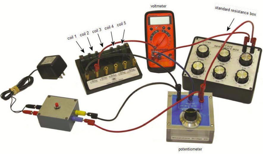
Four coils are made of copper wire and one coil is made of nickel silver
wire. The length and the radius of the wire and the resistivity of the
material for each coil are listed in the table below. You will also
calculate the resistance of each coil from these given material properties.
Data describing the coils
Coil #
|
Type
|
resistivity
(10-8Ωm) |
Length L
m |
Radius
(10-4m) |
| 1 |
copper |
1.7 |
10 |
3.2 |
| 2 |
copper |
1.7 |
10 |
1.6 |
| 3 |
copper |
1.7 |
20 |
3.2 |
| 4 |
copper |
1.7 |
20 |
1.6 |
| 5 |
nickel silver |
33 |
10 |
3.2 |
A schematic diagram of your Wheatstone bridge circuit is shown below.
- Start the experiment by clicking the link.
Wheatstone Bridge
- Choose a coil and a standard resistance R2 (1 Ω, 3 Ω, or 5
Ω).
In the simulation, close the contact
switch (click the OFF/On button) and rotate the potentiometer dial while
observing the reading of the digital voltmeter. Notice that the reading can
be positive or negative. Rotate until you obtain a minimum value close to
zero. (Try to achieve a voltmeter reading of near zero with a potentiometer
dial reading between 3 an 7, by selecting an appropriate standard resistance
R2.)
- When the Wheatstone bridge is balanced, open
and close the switch. The voltmeter reading should always be close to
zero. Record the reading n of the potentiometer dial, and the value of
the standard resistance R2 you selected in the table 2 below for each
coil.
Table 2
Coil #
|
n
|
R2
Ω |
Measured Rx
Ω |
Calculated Rx
R = (ρL/A)(Ω) |
Difference
% |
| 1 |
|
|
|
|
|
| 2 |
|
|
|
|
|
| 3 |
|
|
|
|
|
| 4 |
|
|
|
|
|
| 5 |
|
|
|
|
|
- Find the unknown resistance Rx of
each coil using Rx = R2n/(10 - n). Record this
value in the table 2 under "Measured Rx".
- Using the data in the table describing the coils,
calculate the resistance of each coil.
Use the radius of each wire to compute its
cross-sectional area.
Use the length, the cross-sectional area, and
the resistivity to calculate and record the resistances of each of the
coils of wire.
- Compare the measured and calculated values of the
resistances of each of the coils of wire and calculate the percent
difference.
- Insert Table 2 into your Word document.
Some hints
- Make a statement concerning the relationship
between the resistance of a wire and its length. Support your statement by
referring to your data.
- Make another statement concerning the relationship
between the resistance of a wire and its cross-sectional area. Extend this
statement and relate the resistance of a wire to its diameter or its
radius. Support your statements by referring to your data.
- Is of the following statements true or false?
When a Wheatstone bridge is balanced, no
current flows through the resistance being measured.
Convert your log into a lab report.
See the grading scheme for all lab
reports.
Name:
E-mail address:
Laboratory 6 Report
- In one or two sentences, state the goal of this lab.
- Make sure you completed the entire lab and answered all parts. Make
sure you show your work and inserted and properly labeled relevant tables
and plots.
- Add a reflection at the end of your report in a short essay format.
Save your Word document (your name_lab6.docx), go to Canvas, Assignments, Lab
6, and submit your document.