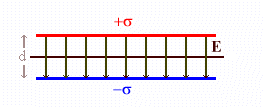
 A
parallel plate capacitor consists of two plates separated by a thin insulating
material known as a dielectric. In a parallel plate
capacitor electrons are transferred from one parallel plate to another.
A capacitor is a device for storing separated charge. No single electronic component plays a more important role today than the capacitor. This device is used to store information in computer memories, to regulate voltages in power supplies, to establish electrical fields, to store electrical energy, to detect and produce electromagnetic waves, and to measure time. Any two conductors separated by an insulating medium form a capacitor.
 A
parallel plate capacitor consists of two plates separated by a thin insulating
material known as a dielectric. In a parallel plate
capacitor electrons are transferred from one parallel plate to another.
The potential difference between the negative and positive plate therefore is given by
∆U = Upos - Uneg = -q ∫negpos E·dr = q E d.
When integrating, dr points from the negative to the positive plate in the
opposite direction from E. Therefore E·dr = -Edr, and
the minus signs cancel.
The positive
plate is at a higher potential than the negative plate.
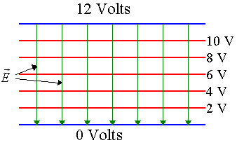 Field lines and equipotential lines for a
constant field between two charged plates are shown on the right. One plate of the capacitor holds a positive charge Q, while the other holds a
negative charge -Q. The charge Q on the plates is proportional to the potential
difference V across the two plates. The
capacitance C is the proportional constant,
Q = CV, C = Q/V.
C depends on the capacitor's geometry and on the type of dielectric material
used. The capacitance of a parallel plate capacitor with two plates of area A
separated by a distance d and no dielectric material between the plates is
C = ε0A/d.
(The electric field is E = σ/ε0.
The voltage is V = Ed = σd/ε0. The charge is Q = σA. Therefore Q/V =
σAε0/σd = Aε0/d.)
The SI unit of capacitance is
Coulomb/Volt = Farad (F).
Typical
capacitors have capacitances in the picoFarad to microFarad range.
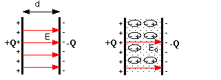 The capacitance tells us how much charge the device stores for a given
voltage. A dielectric between the conductors increases the capacitance of a
capacitor. The molecules of the dielectric material are polarized in the field
between the two conductors. The entire negative and positive charge of the
dielectric is displaced by a small amount with respect to each other. This
results in an effective positive surface charge on one side of the dielectric
and a negative surface charge on the other side of the dielectric. These
effective surface charges on the dielectric produce an electric field, which
opposes the field produced by the surface charges on the conductors, and thus
reduces the voltage between the conductors. To keep the voltage up, more charge
must be put onto the conductors. The capacitor thus stores more charge for a
given voltage. The dielectric constant κ is the ratio
of the voltage V0 between the conductors without the dielectric to
the voltage V with the dielectric, κ = V0/V,
for a given amount of charge Q on the conductors.
In the diagram above, the same amount of charge Q on the
conductors results in a smaller field between the plates of the capacitor with
the dielectric. The higher the dielectric constant κ,
the more charge a capacitor can store for a given voltage. For a parallel-plate
capacitor with a dielectric between the plates, the capacitance is
C = Q/V = κQ/V0 =
κε0A/d = εA/d,
where ε = κε0.
The static dielectric constant of any material is always greater than 1.
Typical dielectric constants
|
|
If a dielectric with dielectric constant κ
is inserted between the plates of a parallel-plate of a capacitor, and the
voltage is held constant by a battery, the charge Q on the plates increases
by a factor of κ.
The battery moves more electrons from the positive to the negative plate.
The magnitude of the electric field between the plates, E = V/d stays the
same.
If a dielectric is inserted between the plates of a parallel-plate of a
capacitor, and the charge on the plates stays the same because the capacitor
is disconnected from the battery, then the voltage V decreases by a factor
of κ,
and the electric field between the plate, E = V/d, decreases by a factor of
κ.
(a) A parallel-plate capacitor initially has a voltage of 12 V and
stays connected to the battery. If the plate spacing is now doubled, what
happens?
(b) A parallel-plate capacitor initially is connected to a battery and the
plates hold charge ±Q. The battery is then disconnected. If the plate spacing is
now doubled, what happens?
Hint: The battery is a charge pump. It can pump charge from one plate
to the other to maintain a constant potential difference.
No battery <--> no charge pump. Charge cannot move from one plate to the
other.
Discuss this with your fellow students in the discussion forum!
External link: PhET Capacitor Lab (Basic)
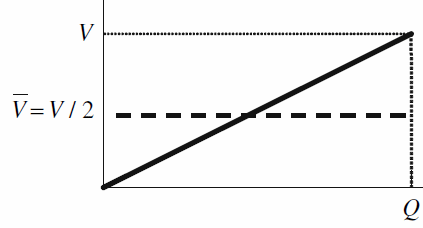 The energy U stored in a capacitor is equal to the work
W done in separating the
charges on the conductors. The more charge is already stored on the plates, the
more work must be done to separate additional charges, because of the strong
repulsion between like charges. At a given voltage, it takes an infinitesimal
amount of work ∆W = V∆Q to separate an additional infinitesimal amount of charge
∆Q.
(The voltage V is the amount of work per unit charge.)
Since V = Q/C,
V increases linear with Q. The total work done in charging the capacitor
is
W = ∫0Qf
VdQ = ∫0Qf (Q/C)dQ = ½(Qf2/C)
= ½VQF = VaverageQf
Using Q = CV we can also write
U = ½(Q2/C) or
U = ½CV2.
Each memory cell in a computer contains a capacitor to store charge. Charge being stored or not being stored corresponds to the binary digits 1 and 0. To pack the cells more densely, trench capacitors are often used in which the plates of a capacitor are mounted vertically along the walls of a trench etched into a silicon chip. If we have a capacitance of 50 femtoFarad = 50*10-15 F and each plate has an area of 20*10-12 m2 (micron-sized trenches), what is the plate separation?
Solution:
For any insulator, there is a maximum electric field that can be maintained without ionizing the molecules. For a capacitor this means that there is a maximum allowable voltage that that can be placed across the conductors. This maximum voltage depends the dielectric in the capacitor. The corresponding maximum field Eb is called the dielectric strength of the material. For stronger fields, the capacitor 'breaks down' (similar to a corona discharge) and is normally destroyed. Most capacitors used in electrical circuits carry both a capacitance and a voltage rating. This breakdown voltage Vb is related to the dielectric strength Eb. For a parallel plate capacitor we have Vb = Ebd.
| Material | Dielectric Strength (V/m) |
|---|---|
| Air | 3*106 |
| Bakelite | 24*106 |
| Neoprene rubber | 12*106 |
| Nylon | 14*106 |
| Paper | 16*106 |
| Polystyrene | 24*106 |
| Pyrex glass | 14*106 |
| Quartz | 8*106 |
| Silicone oil | 15*106 |
| Strontium titanate | 8*106 |
| Teflon | 60*106 |
A capacitor is a device for storing separated charge and therefore storing electrostatic potential energy. Circuits often contain more than one capacitor.
Consider two capacitors in parallel as shown on the right
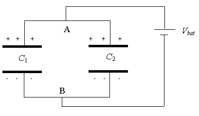 When
the battery is connected, electrons will flow until the potential of point A is
the same as the potential of the positive terminal of the battery and the
potential of point B is equal to that of the negative terminal of the battery.
Thus, the potential difference between the plates of both capacitors is VA - VB = Vbat. We have C1 = Q1/Vbat
and C2 = Q2/Vbat, where Q1 is the
charge on capacitor C1, and Q2 is the charge on capacitor
C2. Let C be the equivalent capacitance of the two capacitors
in parallel, i.e. C = Q/Vbat, where Q = Q1 + Q2.
Then C = (Q1 + Q2)/Vbat = C1 + C2.
For capacitors in parallel, the capacitances add.
For more than two capacitors
we have
C = C1 + C2 + C3 + C4 + ... .
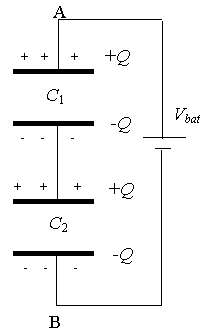 Consider
two capacitors in series as shown on the right.
Let Q
represent the total charge on the top plate of C1, which then induces
a charge -Q on its bottom plate. The charge on the bottom plate of C2
will be -Q, which in turn induces a charge +Q on its top plate as shown.
Let
V1 and V2 represent the potential differences between
plates of capacitors C1 and C2, respectively.
Then V1
+ V2 = Vbat, or (Q/C1) + (Q/C2)
= Q/C, or (1/C1) + (1/C2) = 1/C.
For more than two
capacitors in series we have
1/C = 1/C1 + 1/C2 +
1/C3 + 1/C4 + ... .
where C is equivalent
capacitance of the two capacitors.
For capacitors in series the reciprocal of their equivalent capacitance equals the sum of the reciprocals of their individual capacitances.
What total capacitances can you make by connecting a 5 μF and an 8 μF
capacitor together?
Solution: