Voltage sources
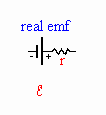 Batteries and other voltage sources have
internal resistance. When they
do work moving charges against the electric force, some of this work is already
converted to thermal energy in the battery. The amount of energy lost to thermal
energy in the battery is Ir, where I is the current flowing in the circuit and r
is the internal resistance of the battery. The voltage across the battery
terminals therefore drops from the nominal value V to (V - Ir) when a current is
flowing in the circuit. In a circuit diagram we represent the internal
resistance of the battery by a resistor r connected in series with the emf.
Electrical Measurements
A voltmeter is a device used to measure voltages, while an ammeter measures
currents. Meters are either analog or digital devices. Analog meters
show the output on a scale with a needle, while digital devices produce a
digital readout. Analog voltmeters and ammeters are both based on a device
called a galvanometer. Digital voltmeters and ammeters generally determine
the voltage drop across a known resistor and then convert the result to a
digital value for display.
 Voltmeters
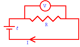
Resistors in parallel have the same voltage across them. If you want to
measure the voltage across a circuit element, such as a resistor, you place the
voltmeter in parallel with the resistor. The voltmeter is shown in a circuit
diagram as a V in a circle, and it acts as another resistor. To prevent
the voltmeter from changing the current in the circuit (and therefore the
voltage across the resistor), the voltmeter must have a resistance much larger
than that of the resistor. If the resistance of the voltmeter is large,
only a negligible current flows through the meter.
 Ammeters
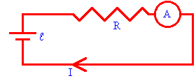
Resistors in series have the same current flowing through them. An
ammeter, must be placed in series with a resistor to measure the current through
the resistor. On a circuit diagram, an ammeter is shown as an A in a
circle. The ammeter acts as a resistor. To prevent the ammeter from
changing the current in the circuit, the ammeter must have a very small
resistance compared to the resistance R of the circuit.
 Ohmmeter
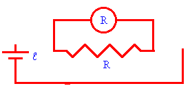
An ohmmeter uses an internal battery to send a known current through the
resistor. The ohmmeter then measures the voltage across the
resistor, and displays the resistance R = V/I. The resistor
must be disconnected from the rest of the circuit.
Electrical safety
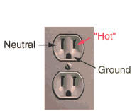 Consider a standard
electrical outlet. The transformer coil, hot wire, appliance, and neutral wire form the circuit. The
neutral return wire is grounded at various places. The ground wire is a separate
path to the ground.
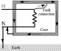
If the electrical equipment housed in a non- conducting case, then the user is
protected, even if a fault inside the case causes the hot wire to touch the
case. But if the equipment is housed in a metallic case, then such a fault can
give a severe shock to the user if the case is not independently grounded. The
user becomes a lowest-resistance path to the ground, and a large current will
flow through the user before (hopefully) the fuse blows.
To prevent such a shock the case must be connected directly to the ground. Then
the lowest-resistance path to the ground is through the case and the user is
protected. Equipment with a metal case either uses a three-prong plug or a
polarized two-prong plug. The prong that makes the connection with the neutral
wire is larger, so that the plug can only inserted one way into the outlet
(without forcing it in).


For equipment with a three prong plug, the case is connected directly to the
ground through the ground wire. For equipment with a two prong plug, the case
is connected directly to the ground through the neutral wire.
 |
|
 |
| The ground wire is tied to the case. |
|
The neutral wire is tied to the case. |
Do not use cheater plugs to plug three prong plugs into two prong extension
cords! While faults are not likely, they can happen. Do not risk it!
 Batteries and other voltage sources have
internal resistance. When they
do work moving charges against the electric force, some of this work is already
converted to thermal energy in the battery. The amount of energy lost to thermal
energy in the battery is Ir, where I is the current flowing in the circuit and r
is the internal resistance of the battery. The voltage across the battery
terminals therefore drops from the nominal value V to (V - Ir) when a current is
flowing in the circuit. In a circuit diagram we represent the internal
resistance of the battery by a resistor r connected in series with the emf.
 Voltmeters
 Ammeters
 Ohmmeter
 Consider a standard
electrical outlet. The transformer coil, hot wire, appliance, and neutral wire form the circuit. The
neutral return wire is grounded at various places. The ground wire is a separate
path to the ground.


