Electromagnetic waves
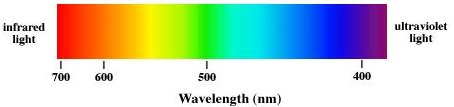
In classical physics light is assumed to be an electromagnetic wave. Electromagnetic waves are categorized according to their frequency f or, equivalently, according to their wavelength λ. The speed of any electromagnetic waves in free space is the speed of light c = 3*108 m/s. Electromagnetic waves can have any wavelength λ or any frequency f as long as λf = c. Visible light has a wavelength range from ~400 nm to ~750 nm. Violet light has a wavelength of ~400 nm, and a frequency of ~7.5*1014 Hz. Red light has a wavelength of ~700 nm, and a frequency of ~4.3*1014 Hz.
Electromagnetic (EM) waves are changing electric and magnetic
fields, carrying energy through space. EM waves require no medium, they
can travel through empty space. Let E denote the electric field
vector and B the magnetic field vector of the EM wave. For
electromagnetic waves E and B are always perpendicular to each
other, and perpendicular to the direction of propagation of the wave.
In general we pay more attention to the electric field
E, because
detectors such as the eye, photographic film, and CCDs interact with the
electric field.
Electromagnetic waves are transverse waves. Transverse waves can be polarized. In this lab you will investigate various polarization effects.
Open a Microsoft Word document to keep a live journal of your experimental procedures and your results. Include all deliverables, (data, graphs, analysis, outcome). Write a 'mini-reflection' immediately after finishing each investigation, experiment or activity, while the logic is fresh in your mind.
Polarization
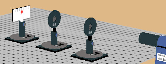
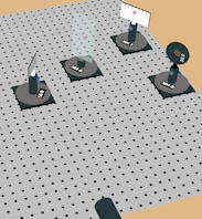
Open the polarization lab simulation. You are presented with a He-Ne laser, an optical breadboard and several optical components. The components can be dragged to different positions on the breadboard and the components can snap to the holes on the breadboard which have a spacing of 1 unit = 2.5 cm. The screen is 4 units wide and 2 units high and the lines on the screen are spaced by ½ unit. Clicking anywhere on the breadboard you can rotate and zoom the view. A transparent viewer can help you align the beam. All components can be translated and rotated, and the post holders can be raised and lowered with the mouse.
The He-Ne laser beam (λ = 633 nm) is unpolarized. You have 3 (ideal) linear polarizers and a power meter with a Bluetooth connection to a digital readout to monitor the beam intensity. You can also monitor the intensity of the laser beam on a screen (corrected for the average response of the human eye to light). The polarizers are mounted in a rotation stage. The transmission axis of the polarizers is horizontal when the rotation stage reads zero. You can explore what happens to the transmitted intensity if you rotate a third polarizer between two crossed polarizers and you can verify the Law of Malus. You can also reflect the laser beam off a glass slide and explore polarization by reflection. The back of the glass slide is painted black to absorb the transmitted portion of the beam. The slide is made of high-index of refraction glass, you can measure the index of refraction by finding the the Brewster angle.
Activity 1:
If light propagates through a transparent material such as water or glass, it
interacts in various ways with the atoms or molecules that make up the material.
This interaction can be wavelength and polarization dependent. Due to the
interaction, light moves through a transparent material with an apparent speed v = c/n.
The index of refraction n is a property of the material. It is greater
than 1, so that v is less than c. In most transparent materials the index
of refraction depends slightly on the wavelength of the light, and in some
materials it depends on the polarization.
Linear polarization: An
ideal linear polarizer is a material that passes only light waves for which the electric
field vector is parallel to its transmission axis. If E0 is the incident
field vector and the angle between E0 and the transmission
axis is θ, then the magnitude of transmitted field
vector is E0 cosθ, and its direction is the
direction of the transmission axis. The intensity I of an electromagnetic wave
is proportional to the square of the magnitude of the electric field vector. We
therefore have
Itransmitted = I0 cos2θ.
 |
 |
 |
| Polarizers with parallel transmission axes |
Polarizers with perpendicular transmission axes |
Polarizer 3 between polarizers 1 and 2. |
Spend a few minutes exploring what happens to the intensity of the beam spot on the screen as you pass the beam first through one and then through two polarizers. Observe the change in transmitted light intensity as either of the polarizers is rotated. This combination acts as a "light valve."
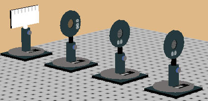
Place a third polarizer between two crossed polarizers and rotate the transmission axis of the third polarizer while observing the intensity of the beam spot on the screen.
Activity 1 Deliverables: (to be included in the your journal)
-
Visuals:
- Screenshot of the 2 polarizer setup when the transmitted intensity is zero.
- Screenshot of the 3 polarizer setup when the transmitted intensity is maximum.
- Analysis: A brief description of your observations.
Experiment 1:
In this experiment you will use a linear polarizer to produces a polarized beam and then pass this beam through a second polarizer whose transmission axis makes an angle θ with respect to the transmission axis of the first one. You will check that Itransmitted = I0 cos2θ. This is called the Law of Malus.
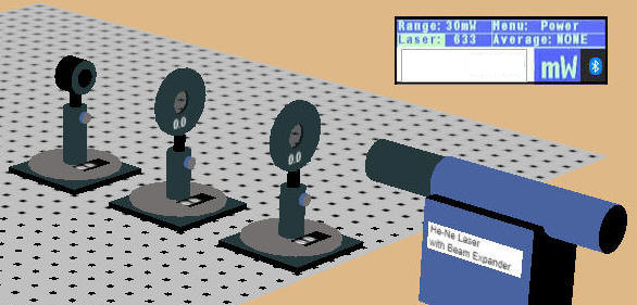
Use the setup shown in the picture above. It uses the power meter to monitor the beam intensity. You can increase the spacing between the components to make it easier to rotate the polarizers. Start with the transmission axes of both polarizers horizontal (zero degrees). If necessary, adjust the height of all components so that the beam falls onto the power meter and the meter reads 0.9 mW. (Note: The readout position is fixed, you cannot drag it around.)
After the laser light has passed through the polarizers, it is ~100% polarized along the horizontal direction, since the transmission axis of each polarizer is horizontal.
In Excel create a table. You can download the first row here.
| angle (deg) | angle (rad) | I (mW) | I0*cos2(angle) |
- You will now rotate the second polarizer with respect to the first one. Start by recording the measured intensity for zero degrees, when both polarizers are aligned.
- Rotate the second polarizer. Your objective is to map out the mathematical relationship between the relative angle of two polarizers and the intensity of the light that passes through. Decide on a data-collection strategy. How many data points do you need, and at what intervals, to confidently map this curve? Record the angle and the the intensity I for each step in the table.
- Calculate I0*cos2(angle), with the angle in radians. I0 is the intensity you measured when the second polarizer angle was 0.
- Create a plot of I and I0*cos2(angle) versus angle (rad). Label the axes.
Experiment 1 Deliverables: (to be included in the your journal)
- Visuals: Your plot of intensity versus angle.
- Analysis: Have you verified the Law of Malus? How can you tell? No experiment is perfect, there are always uncertainties. Are your uncertainties small enough so that you can tell one way or the other. If a skeptic looked at your graph and claimed that light intensity is simply a linear function of angle between 0o and 90o, how would would you use your experimental results with their uncertainties to prove them wrong?
 Polarization by reflection
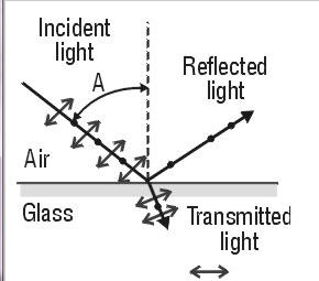
When unpolarized light is incident on a boundary between two transparent materials, for example on an air-glass boundary, then the reflected and transmitted components are partially plane polarized. The reflected wave is 100% linearly polarized when the incident angle is equal to the Brewster angle θB, where tanθB = n2/n1. For a air-glass boundary, tanθB = nglass. The Brewster angle for reflecting off glass is between 55o and 60o.
Experiment 2:
You will reflect the laser light off a glass slide You will make sure that the
incident angle is close to the Brewster angle and verify that light polarized in
the plane of incidence it will not be reflected at the Brewster angle. The
plane of incidence is a plane perpendicular to the reflecting surface that
contains the incident beam.
If the reflecting surface is horizontal, for example if sunlight is reflecting
at a low angle off a lake, then the
plane of incidence is vertical. The reflected light is horizontally polarized and can be blocked by a polarizer with
a vertical transmission axis. If the reflecting surface is vertical, as
for our glass slide, then
the plane of incidence is horizontal, and horizontally polarized light
will not be reflected at the Brewster angle. Then
the reflected light is vertically polarized and can be blocked by a polarizer
with a horizontal transmission axis. You will reflect the laser light off
a vertical glass slide and find the Brewster angle.
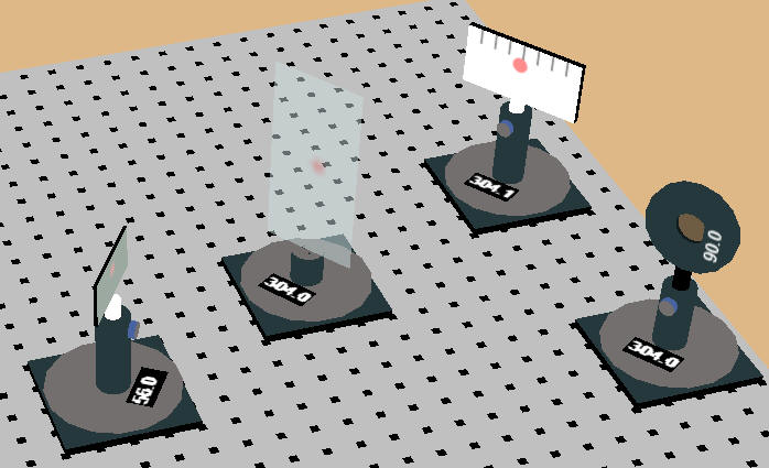
- Set up the components as shown above. Rotate the glass slide post by an angle between 55 and 60 degrees. Rotate the posts of the screen and a polarizer by the same amount in the opposite direction.
- Position the screen so that you can see the reflected beam on the screen. You can use the viewer to help you find the reflected beam.
- Remove the viewer and put the polarizer in its place. Make sure that the beam passes through the polarizer and you can still see it on the screen. If you need a finer position adjustment to accomplish this, uncheck snap to grid in the upper right corner of your screen.
- Rotate the polarizer in front of the screen by 90o to 180o, so that its transmission axis is horizontal. It now blocks vertically polarized light.
- If with the transmission axis horizontal you can still see a faint beam on the screen, try a slightly different angle for the glass slide post. When you adjust this angle make sure that the beam still passes through the polarizer onto the screen. Rotate the polarizer transmission axis back to vertical to check. You may have to adjust the position of the screen and the polarizer.
- Iterate until the reflected intensity is practically zero and you can no longer see the beam on the screen with the polarizer transmission axis horizontal, but you can see the beam when the polarizer transmission axis is vertical.
- Record the glass slide post angle for this situation. This is the Brewster angle θB for the glass slide in air.
- Use your measured value of θB to find the
index of refraction of the glass slide.
We have tanθB = nglass. - Keep the rotation stage fixed at the Brewster angle and rotate the polarizer. You should see a reflected beam. At the Brewster angle the reflected beam is 100% vertically polarized.
Experiment 2 Deliverables: (to be included in the your journal)
- Visuals: A screenshot of your setup at the Brewster angle.
- Analysis: Discuss your result. Is your value for nglass reasonable?
Imagine you are a product engineer designing polarized sunglasses for drivers looking at sunlight reflecting off a flat, wet asphalt road. Based on your results from Experiment 2, should the transmission axis of the sunglasses' filters be oriented vertically or horizontally to eliminate the glare? Use the specific polarization behavior of reflected light you observed to defend your engineering choice. - Outcome: Your measured nglass.