Studio Session 3
Circuit elements
 Our bodies separate and store charge as a power source to transmit signals
along nerves. An excess of positive ions on the outside
of the cell membrane results in a potential difference across the membrane.
The inside of the cell is at a negative potential of ~100 mV with respect to the
outside. The membrane acts like a capacitor.
Our bodies separate and store charge as a power source to transmit signals
along nerves. An excess of positive ions on the outside
of the cell membrane results in a potential difference across the membrane.
The inside of the cell is at a negative potential of ~100 mV with respect to the
outside. The membrane acts like a capacitor.
Electrical signals play a
role in transmitting information through our bodies. Sensory
information is transmitted via nerves. Each nerve consists of a
bundle of nerve cells or neurons. A neuron receives stimuli at the
input end and produces a signal that is transmitted across the axon to
the output end. The axon membrane can be modeled as a charged
capacitor. When the neuron is stimulated, the voltage across the
capacitor rapidly changes and the charge on the plates reverses, only to
thereafter quickly return back to its original value. For this to
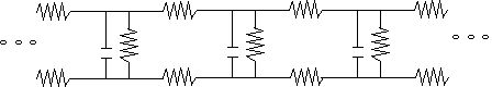
happen, a current must flow through some effective resistance. The
whole axon can be modeled as a chain of capacitors and resistors
connected in series and parallel. A voltage and current pulse
propagates along this chain.
 The speed of propagation of the
action potential depends on the electrical resistance R within the core
of the axon and the capacitance C across the membrane. A simple
electrical circuit, consisting of a resistor in series with a capacitor,
has a time constant τ = RC. The
time constant characterizes the time it takes for the capacitor to
charge and discharge and therefore limits the maximum speed with which
signals can travel through the circuit.
The speed of propagation of the
action potential depends on the electrical resistance R within the core
of the axon and the capacitance C across the membrane. A simple
electrical circuit, consisting of a resistor in series with a capacitor,
has a time constant τ = RC. The
time constant characterizes the time it takes for the capacitor to
charge and discharge and therefore limits the maximum speed with which
signals can travel through the circuit.
In this laboratory you will investigate the behavior
of simple circuits containing resistors and capacitors. While you
will not model neurons directly, you will become more familiar
with how circuits in general behave, and therefore also with how neuron circuits behave.
Equipment needed:
- Digital multimeter
- Pasco RLC circuit board
- Pasco voltage sensor
- 3 patch cords (1 black, 1 red, 1 yellow)
Open a Microsoft Word document to keep a log of your experimental procedures,
results and discussions. This log will become your lab report. Address the
points highlighted in blue. Answer all questions.
The resistance of your body
Fatal electric shock occurs when a sufficiently large electric
current flows through the body. A fraction of such a current flows through the
heart and may disrupt the cardiac cycle. Typical effects are listed in the
table below.
| Shocking current: |
Effect: |
| <1 mA |
no observable effect |
| ~1 mA - ~10 mA |
tingling sensation |
| ~10 mA - ~100 mA |
muscular paralysis
("can't let go") |
| ~100 mA |
ventricular fibrillation |
| ~1A - ~10 A |
thermal damage to tissue |
Paradoxically, brief currents of > 1 A may be less dangerous than lower
currents. Instead of putting the heart into ventricular fibrillation, these currents clamp the whole heart muscle at the same time. When the
current is turned off, a normal heart beat may resume on its own accord.
Indeed, currents of about 1 A are used clinically to defibrillate the heart.
Experiment 1
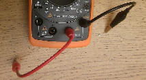 Use the digital multimeter to measure the resistance of your body.
Switch the meter on the 20 MΩ scale.
Make sure the leads are plugged into the Ω and COM
connectors on the lower right of the meter.
Use the digital multimeter to measure the resistance of your body.
Switch the meter on the 20 MΩ scale.
Make sure the leads are plugged into the Ω and COM
connectors on the lower right of the meter.
Note: This multimeter is only for
measuring components not connected to a power source. Do not
connect it to a circuit that has power.
Press the thumb of one of your
hands against the black and the thumb of the other hand against the red lead.
Record the values for each member of your group with dry and with wet
thumbs.
- Predict the current that would flow through your body if you held
one terminal of a 1.5 V battery in one of your hands and the other terminal in
the other hand.
- Predict the current that would flow through your body if you held one terminal
of a 110 V power source in one of your hands and the other terminal in the other
hand.
The salty fluids within the human body are electrical conductors. Salt
water conducts electricity because it has mobile electrons and ionic states via
the salt atoms. Salt water provides a large surface area of contact for
the conductive element and it connects with the sweat glands so electricity can
flow past the skin and into your body, which has low electrical resistance. The internal resistance of an arm (from hand to shoulder) is less than 100 Ω. If there is a voltage across this internal resistance, a current will flow and
heat will be generated. If the current is large or the connection time is long
enough, this heat will cause burns and destroy tissue. Fortunately the
resistance of dry skin is high. The dry protein of your skin is an
insulator. Using a typical contact area, the skin acts
like an approximately (10 - 100) kΩ resistor in series with the internal
resistance of the body. At voltages below about 50 V the dry skin
provides safe current limiting protection.
Be extremely careful not to have electrical contact with a voltage
source if you have wet or sweaty skin.
Measuring capacitance
 Assume you connect two identical metal plates of area A, separated by a non-conducting
material which has a thickness d to a battery and a switch, as shown.
Assume you connect two identical metal plates of area A, separated by a non-conducting
material which has a thickness d to a battery and a switch, as shown.
When the switch is open,
there is no excess charge on either plate.
Discuss
what happens when the switch is then closed.
Experiment 2
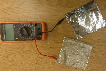 Construct a parallel plate capacitor out of two rectangular pieces
of metal foil. The sheets have small "handles".
Attach the leads of the multimeter to those handles and
make sure the leads are plugged into the + and - connectors on the lower left of
the meter. Switch the multimeter to the 20 nF scale.
Construct a parallel plate capacitor out of two rectangular pieces
of metal foil. The sheets have small "handles".
Attach the leads of the multimeter to those handles and
make sure the leads are plugged into the + and - connectors on the lower left of
the meter. Switch the multimeter to the 20 nF scale.
Note: The metal foil has sharp edges.
Be careful not to cut yourself.
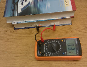 Slip the two foil sheets between
the pages of a heavy textbook and separate them by 3 pages of the book. Make sure the
foil sheets do not touch each other and "short out".
The areas of the sheets should overlap and the "handles" should stick out on
opposite sides. Weight the book
down with another heavy textbook.
Slip the two foil sheets between
the pages of a heavy textbook and separate them by 3 pages of the book. Make sure the
foil sheets do not touch each other and "short out".
The areas of the sheets should overlap and the "handles" should stick out on
opposite sides. Weight the book
down with another heavy textbook.
(a) Measure the capacitance of your "parallel plate capacitor"
using your multimeter. Record your
measured value.
(b) Investigate how the capacitance depends on the separation
between the two foil sheets. Take data for at least five different separation
distances (in units of number of pages). Make sure everything except the separation
of the two foils stays the same. Record your data in a table in
your log. Record the dimensions of the foil and calculate its area.
(c) Use Excel to produce a plot of capacitance C in units of nF versus
d in units of number of pages and versus 1/d. Paste the graphs into your
log. Is either of these graphs
linear?
| number of pages: |
Capacitance (nF) |
| 3 |
|
| 6 |
|
| 9 |
|
| 12 |
|
| 15 |
|
(d) Investigate how the capacitance depends on the area of the conducting
plates. Use a separation distance of 3 pages and change the overlap area
of the plates to approximately ½ and 1/4 of the total area.
Just move the foils, do NOT fold them.
Record your data in a table in your log.
Ohm's law
Ohm discovered that when the voltage (potential difference) across a
conductor changes, the current flowing through the conductor changes. He
expressed this as I = V/R or V = IR. As the voltage increases, so does the current. For many
conductors R is approximately constant. These materials are called ohmic.
If the voltage across an ohmic resistor is increased, a plot of voltage versus
current shows a straight line. The slope of the line is equal to R.
For non-ohmic materials, R is not constant and a plot of voltage versus current
will not show a straight line.
Experiment 3
Use the Pasco RLC board to investigate the relationship between
current and voltage in ohmic and non-ohmic materials.
Note: All the plots you produce must be inserted into your log.
- Make sure the Pasco 850 interface is turned on. Open the
Capstone program. The icon for this program is on the desktop.
- In the Hardware Setup window click on the yellow circle over the two output jacks on the image of the
PASCO 850 interface.
Select the Output Voltage - Current Sensor.
- Plug a black patch cord into the left output and a red patch cord
into the right output.
- Click Hardware Setup again to close this window. In the
Control Panel at the bottom set the sample rate to 1000 Hz = 1 kHz.
- Click on the Signal Generator icon in the tool panel, (4 icons below
Hardware Setup), and choose the 850 Output 1.
- Choose the Triangle Wave, set the amplitude
to 3 V, the frequency to 1 Hz. Click AUTO to turn it on automatically.
- Close the signal generator window and click on Classic templates, two small
and one large
display, graphs.
- For the vertical axis of one small graph choose Output Voltage (V).
For the vertical axis of
the other small graph
choose Output Current (A). For both small graphs choose time for the
horizontal axis.
- For the large graph choose Output Voltage (V) for the vertical and Output
Current (A) for the horizontal axis.
- Click the Recording Conditions icon in the control panel.
Choose Start Condition, Measurement Based,
Output Voltage (V) is above 0.2 V.
Choose Stop Condition, Time Based, 3 s.
- Connect the 10 Ω resistor to the output of the interface as shown below.
- Click the Record button.
- You will record data for 3 seconds.
- Click the "autoscale" button in the graph displays to rescale the
graphs.
- In V versus A graph choose a linear fit and click on Fit. The slope of
the large V versus A graph will be displayed.
- Give your large graph of voltage versus
current a title and copy it into your Word document.
- Repeat the measurement with the 100 Ω resistor connected to the output of the interface.
- Answer the following questions:
- Are the 10 Ω and 100 Ω resistor ohmic resistors? Why or why not? Base your
conclusions on your measurements.
- Do the resistances found from the slope of
the voltage versus current graphs agree with the nominal resistances
written on the RLC board? What are the percentage differences?
- Now connect the light bulb on the RLC board to
the output of the interface and take data for 3 s.
Repeat the measurement a few times, and alternately watch the bulb
and the trace on your large graph.
- Give your large graph of voltage versus
current a title and copy it into your Word document.
- Answer the following questions
- Is the bulb an ohmic resistor? Why or why not? Base your conclusions
on your measurements. Describe your observations.
- Can you determine the resistance of the bulb?
- Now erase all your data and connect the LED on the RLC board to
the output of the interface and take data for 3 s.
- Repeat the measurement a few times, and alternately watch the LED
and the trace on the graph 3.
- Describe your observations.
- Change the signal generator amplitude to 5 V and repeat.
- Describe your observations.
- Is the LED an ohmic resistor? Why or why not? Base your
conclusions on your measurements.
RC circuits
Find out how the voltage across a capacitor varies as it charges and
discharges.
Experiment 4
- Connect the 330 μF capacitor and the 100 Ω resistor in series to the
output of the interface as shown below.
Note: You have to short out the coil.
- In the Signal Generator window choose the
square wave.
- Choose an amplitude of 2 V and a frequency of 2 Hz.
Under Offsets and Limits adjust the voltage offset to be 2 volts.
- In the Capstone program, click the Hardware Setup button on the left, double
click Analog Channel A and choose to add the Voltage
Sensor.
- Plug the Voltage Sensor into Analog Channel A.
- Connect the voltage sensor across the capacitor as shown below.
- Change the axes of your large graph. Choose Voltage (Ch A) for the
vertical axis and time for the horizontal axis.
- Click the Recording Conditions icon and choose Stop Condition, Time Based, 1 s.
- Click the Record button. You will record data for 1 s. The power supply will
turn on for 1/4 s, then turn off for 1/4 s then turn on again for 1/4 s
and so on. During the time the power supply is off the RC circuit is shorted
out. The capacitor will charge when the power supply is on and discharge
when it is off.
- Click the "autoscale" button in your graphs to rescale the display.
Magnify a region of the plot of voltage
versus time that shows the voltage rising from zero volts to the maximum
voltage.
- Use the smart cursor to find the time t1 when the voltage
begins to rise and the time t2 when the voltage has reached
½ of its maximum value.
Find t½ = t2 -
t1.
- Use t½ = τ*ln2 = 0.693*τ
to find the time constant τ.
- Answer the following questions:
- What value did you find for τ? Does
this value agree with the nominal value τ = RC?
Note: The stated values of the capacitance may vary by as much as
20% from the actual value.
- Check your value of t½ obtained from the voltage versus
time plot by also obtaining it from the output current versus time plot.
How long does it take for the current to decrease to ½ its maximum value?
Do you get the same value for t½?
Convert your log into a lab report.
See the grading scheme for all lab
reports.
Name:
E-mail address:
Laboratory 3 Report
- In one or two sentences, state the goal of this lab.
- Make sure you completed the entire lab and answered all parts. Make
sure you show your work and inserted and properly labeled relevant tables
and plots.
- Add a reflection at the end of your report in a short essay format.
Save your Word document (your name_lab3.docx), go to Canvas, Assignments, Lab
3, and submit your document.