Resistors in series and parallel
 The circuit elements
we have considered thus far
are the emf
(power supply or battery), the resistor (any device that converts
electrical energy into thermal energy),
and the capacitor (a device for storing separated charges). In circuit diagrams they are represented by the symbols
shown on the right.
 Most interesting circuits consist of more than just one
emf and one resistor. Some circuits have more than one resistor
connected in
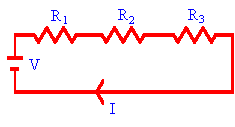
series, as shown in the figure on the right. In such a circuit the
same current I flows through each resistor. The
potential difference across resistor 1 is V1 = IR1, the
potential difference across resistor 2 is V2 = IR2, and
the potential difference across resistor 3 is V3 = IR3. The potential difference across the chain is equal to the battery voltage V.
We have V = V1 + V2 + V3 = IR1 + IR2
+ IR3. The equivalent resistance
of the circuit can be calculated from V = IR. The two equation yield
R = R1 + R2 + R3.
The equivalent resistance of any number of resistors
connected in series is the sum of their individual resistances.
It is always
greater than any of the individual resistances.
Example:
In the figure above, let R1 = 4 Ω, R2 = 4 Ω, and R3
= 12 Ω. Then the equivalent resistance is R = 20 Ω.
If the
battery voltage is 10 V, then the current in the circuit is I = V/R =
(10 V)/(20 Ω) = 0.5 A.
The current through each resistor is 0.5 A. The power
dissipated is P = IV = 5 W.
Assume another 20 Ω resistor is added to the chain. Adding another
20 Ω resistor increases the equivalent resistance to R = 40 Ω. The
current drops to I = (10 V)/(40 Ω) = 0.25 A. The power dissipated drops to
P = 2.5 W.
Adding an additional resistance in series
- reduces the current in the circuit,
- reduces the power I2Ri dissipated by each of the i
resistances Ri,
- reduces the total power dissipated.
The light bulbs in a chain of Christmas lights are often connected in series. If 10 identical light bulbs are in the chain and the voltage across the chain is
120V, then the voltage across each bulb is 12 V. The same current
flows through each bulb. If one bulb burns out, no current flows, and none
of the bulbs will light up.
 It is more common to have more than one resistance connected in
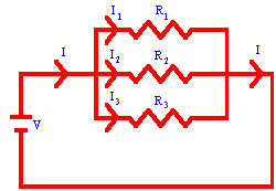
parallel, as shown in the figure to the
right. The current I from the battery is divided into I1, I2,
and I3 flowing through R1, R2, and R3,
respectively. These three currents recombine when the branches meet again.
I = I1 + I2 + I3.
The voltage across each resistor in the parallel circuit shown is equal to
the battery voltage V.
We have I1 = V/R1, I2
= V/R2, I3 = V/R3. We find the
equivalent resistance from V = IR,
1/R = I/V = (I1 + I2 + I3)/V
= (1/R1) + (1/R2) + (1/R3).
1/R = (1/R1) + (1/R2) +
(1/R3).
For a set of parallel resistors the reciprocal of their
equivalent resistance equals the sum of the reciprocals of their individual
resistances.
Note: The equivalent resistance of any parallel combination of resistors is
always less than any of the individual resistances.
Example:
Assume that in the circuit shown on the right R1 = 8 Ω, R2
= 8 Ω, and R3 = 4 Ω.
Then 1/R = 1/(8 Ω) + 1/(8 Ω) + 1/(4 Ω) =
1/(2 Ω). R = 2 Ω.
If the battery voltage is 10 V, then the current in
the circuit is I = V/R = (10 V)/(2 Ω) = 5 A.
The individual currents are found
from Ii = V/Ri. The voltage across each resistor is 10
V, therefore
I1 = (10 V)/(8 Ω) = 1.25 A,
I2 =
(10 V)/(8 Ω) = 1.25 A,
I3 = (10 V)/(4 Ω) = 2.5 A.
The currents add to yield the total current I = 5 A.
If another 8 Ω resistor is added in parallel, a current of 1.25 A will
flow through this resistor. The total current in the circuit
increases, the equivalent resistance decreases, and the power P = IV
dissipated by the circuit increases.
If 10 Christmas lights are connected in parallel, then one burned-out bulb
does not prevent the other bulbs from lighting up. However, a different
type of bulb must be used if the bulbs are to be connected parallel to a 120 V
outlet, because the voltage across each bulb will be 120 V.
 Often circuits contain
one emf and a number of
series and parallel connections. An example is the section
of a circuit shown on the right. The total resistance of such a circuit can be found by sequentially replacing
parts of the circuit with a single equivalent resistance. The equivalent circuit
then consists of a single emf and a single resistor. This procedure yields the
total current flowing in the circuit, and the currents flowing through the
individual resistors can be found by reversing the reduction process.
 Let us find the total resistance between the points A and B in the
circuit to the right.
R1 and R2 are in series and are
replaced by R12 = R1 + R2.
Now R12 and R3 are in parallel and can be replaced
by R, where 1/R = 1/R12 + 1/R3.
If R1 = R2
= R3 = 1 Ω, then R12 =
2 Ω and R = (2/3) Ω.
If a 6 V battery is connected across points A and B, then
the current flowing in the circuit is I = V/R = 9 A.
The current flowing
through R3 is I = V/R3, the current flowing through R1
and R2 is V/R12 = 3 A.
General rules for finding the equivalent resistance of a simple circuit:
- Two (or more) resistors with their heads directly connected together and
their tails directly connected together are in parallel. They can be
replaced by one equivalent resistor R using 1/R = (1/R1) + (1/R2) + (1/R3) + ....
- Two (or more) resistors connected together so that the tail of one is
connected to the head of the next, with no other path for the current to
take along the line connecting them, are in series. They can be replaced by
one equivalent resistor R using R = R1
+ R2 + R3+....
- For resistors in series, the same current flows through each resistor,
and for resistors in parallel, the same voltage drops across each resistor.
Problem:
What are the largest and smallest resistances you can obtain by
connecting a 36 Ω, a 50 Ω, and a 700 Ω resistor together?
Solution:
- Reasoning:
To obtain the largest resistance, we have to connect the resistors in
series.
To obtain the smallest resistance, we have to connect the resistors in
parallel.
- Details of the calculation:
Rlargest = (36 + 50 + 700) Ω = 786 Ω.
1/Rsmallest = (1/36 + 1/50 + 1/700) Ω-1 = 0.0492/Ω.
Rsmallest = 20.32 Ω.
Embedded Question 3
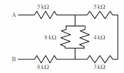
What is the equivalent resistance between the points A and B?
Discuss this with your fellow students in the discussion forum!
Discuss the rules for finding the equivalent resistance of multiple resistors in
series and parallel.
Kirchhoff's rules
 A junction in a circuit is a
point where at least three circuit paths meet. A
branch is a path connecting two junctions. The
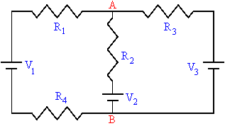
circuit on the right has two junctions, labeled A and B, and three branches, namely the
three different paths from A to B. This circuit is a multi-loop circuit,
with more than one battery in different branches of the circuit. To
analyze such a circuit and to find the currents in all branches of the
multi-loop circuit one must use Kirchhoff's rules.
- Kirchhoff's first rule:
Junction rule:
At any junction point in a circuit where the current can divide, the sum of
the currents into the junction must equal the sum of the currents out of the
junction. (This is a consequence of charge conservation. "What flows
in, has to flow out.")
- Kirchhoff's second rule:
Loop rule:
When any closed circuit loop is traversed, the algebraic sum of the
changes in the potential must equal zero. (This is a consequence of
conservation of energy. The electric force is a conservative force.
Once a reference point has been chosen, the potential depends only on the
position.)
Kirchhoff's rules apply to all circuit.
General procedure for analyzing a circuit using Kirchhoff's rules:
- Replace any combination of resistors in series or parallel with their
equivalent resistance. Label each remaining resistor and each emf with
a symbol.
- Choose a direction for the current in each branch of the circuit, and
label each current.
- Add plus and minus signs to label the high and low potential sides of
each circuit element, (i.e. each emf, resistor, capacitor). Label the
side of the resistor on which the current enters with a plus sign (+) and
the side on which the current exits with a minus sign (-).
- Sometimes it is hard to predict in which direction the current will
flow in a particular loop. Simply pick a direction.
If the real current flows in the opposite direction, the current in your
solution will be negative. The minus sign just indicates that the
current flows in the direction opposite to the one you picked.
- Apply Kirchhoff's first rule to all but one of the junctions in the
circuit.
- Each time you use the junction rule a current that has not been used
before must be included.
- Apply Kirchhoff's second rule to as many loops as needed to obtain as
many equations (including the junction equations) as you have unknowns.
- Each time you use the loop equation you have to include a circuit
element that has not been used before.
- To write down a loop equation, you choose a starting point, and then
follow a path around the loop in one direction until you get back to the
starting point. As you cross a battery or a resistors note the
change in voltage. If you cross from - to +, the change is
positive. If you cross from + to -, the change is negative.
Add these changes in voltage and set the sum equal to zero.
- Solve the equations to obtain the values of the unknowns.
Example:
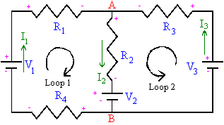 In the circuit
to the right, let V1 be a 1 V battery, V2 be a
2 V battery, V3 be a 3 V battery, and let each resistor be a 1 Ω resistor.
Pick directions for the currents as shown in the diagram.
- Junction A: I1 + I3 = I2.
- Loop 1: V1 - I1R1 - I2R2
- V2 - I1R4 = 0.
This yields
1V - I11 Ω - I21 Ω - 2 V - I11 Ω = 0, or 2I1
+ I2 = -1 A. (Units: V/Ω = A)
- Loop 2: V3 - I3R3 - I2R2
- V2 = 0.
This yields
3V - I31 Ω - I21 Ω - 2 V = 0, or I3 + I2
= 1 A.
- We now have to solve the three equations,
I1 + I3 = I2,
2I1 + I2 = -1 A,
I3 + I2 = 1 A,
for the three unknown currents.
- Eliminate I3: I3 = 1 A - I2 using
the third equation. The first two equations then yield
I1 + 1 A - I2 = I2, I 1- 2I2
= -1 A,
2I1 + I2 = -1 A.
- Eliminate I2: I2 = -1 A - 2I1.
We now can solve for I1.
I1 + 2 A + 4I1 = -1 A, 5I1 = -3 A, I1
= -(3/5) A.
- Now we can solve for I2 and I3.
I2 = -1 A - 2I1 = -1 A + (6/5) A = (1/5) A
I3 = I2 - I1 = (4/5) A
- I2 and I3 flow in the directions picked in the
diagram, I1 flows in a direction opposite to the one picked in
the diagram.
 The circuit elements
we have considered thus far
are the emf
(power supply or battery), the resistor (any device that converts
electrical energy into thermal energy),
and the capacitor (a device for storing separated charges). In circuit diagrams they are represented by the symbols
shown on the right.
 Most interesting circuits consist of more than just one
emf and one resistor. Some circuits have more than one resistor
connected in
series, as shown in the figure on the right. In such a circuit the
same current I flows through each resistor. The
potential difference across resistor 1 is V1 = IR1, the
potential difference across resistor 2 is V2 = IR2, and
the potential difference across resistor 3 is V3 = IR3. The potential difference across the chain is equal to the battery voltage V.
We have V = V1 + V2 + V3 = IR1 + IR2
+ IR3. The equivalent resistance
of the circuit can be calculated from V = IR. The two equation yield
 It is more common to have more than one resistance connected in
parallel, as shown in the figure to the
right. The current I from the battery is divided into I1, I2,
and I3 flowing through R1, R2, and R3,
respectively. These three currents recombine when the branches meet again.
 Often circuits contain
one emf and a number of
series and parallel connections. An example is the section
of a circuit shown on the right. The total resistance of such a circuit can be found by sequentially replacing
parts of the circuit with a single equivalent resistance. The equivalent circuit
then consists of a single emf and a single resistor. This procedure yields the
total current flowing in the circuit, and the currents flowing through the
individual resistors can be found by reversing the reduction process.
 Let us find the total resistance between the points A and B in the
circuit to the right.
 A junction in a circuit is a
point where at least three circuit paths meet. A
branch is a path connecting two junctions. The
circuit on the right has two junctions, labeled A and B, and three branches, namely the
three different paths from A to B. This circuit is a multi-loop circuit,
with more than one battery in different branches of the circuit. To
analyze such a circuit and to find the currents in all branches of the
multi-loop circuit one must use Kirchhoff's rules.
 In the circuit
to the right, let V1 be a 1 V battery, V2 be a
2 V battery, V3 be a 3 V battery, and let each resistor be a 1 Ω resistor.
Pick directions for the currents as shown in the diagram.