The magnetic flux through an area can change because the field strength is
changing, or because the direction of the field is changing. Rotating a
permanent magnet in front of a wire loop, or rotating a wire loop in front of a
permanent magnet will result in a change of the magnetic flux through the loop. This change in flux produces an emf and a current will start flowing in the loop. We have an electric generator. The basic
function of a generator is to convert mechanical energy into electrical energy.
A simple electric generator is shown in the figure on the right.
Mechanical energy is needed to rotate the coil of wire located between the
pole faces of a permanent magnet. The magnetic flux through the plane of the
coil has its maximum value when this plane is perpendicular to the magnetic
field lines between the poles. As the coil turns and the plane of the coil
becomes parallel to the field lines, the flux becomes zero. As the coil
continues to turn, the field lines pass through the coil in the direction
opposite to the initial direction. The coil's rotation causes the magnetic flux
passing through the coil to change continuously from a maximum in one direction,
to zero, to a maximum in the opposite direction, and so on. An emf is induced in
the coil because of this changing magnetic flux. The magnitude of the induced
emf is proportional to the rate of change of the magnetic flux. The faster the
coil turns, the larger the maximum value of the induced emf, since increased
angular speed causes the magnetic flux to change more rapidly.
The figure on
the right shows plots of the continuously varying magnetic flux and
the induced emf versus time. By Faraday's law, the magnitude of the induced emf
is equal to the rate of change of magnetic flux, so its maximum values occurs
when the flux curve has its greatest slope. The induced emf goes through zero
when the flux curve has zero slope. We observe a 90o phase shift
between flux and induced emf. If the coil of the generator is part of a closed circuit, and a current flows
in the circuit, the coil becomes a magnetic dipole with dipole moment
m = IAn in a magnetic field. A torque
τ = μ × B
is trying to align this dipole with the magnetic field. The coil has to be
turned, and mechanical work has to be done against this torque. The lower the
resistance of the circuit, the more current flows and the more mechanical work
has to be done. The rate at which mechanical work has to be done is equal to the
power dissipated by the circuit.
The emf produced by a generator is an alternating
emf. This is one reason that we have an AC (alternating current)
power distribution system. For power production in the US, the angular velocity
of the generator coils is 60*2π/s.
The frequency is 60 Hz. The electric generators used in power plants resemble the
simple one we have described here. Usually they have more than one coil and the
magnets are electromagnets rather than permanent magnets but the principle of
operation is the same.
The same basic device can be used as an electric motor or as an electric
generator. At the heart of both a motor and a generator is a wire coil in a
magnetic field. When the device is used as a motor, a current is passed through
the coil. The interaction of the magnetic field with the current causes the coil
to spin. To use the device as a generator, the coil is spun, inducing a current
in the coil.
A spinning motor also acts like a generator. The coils of the motor turn in a
magnetic field. Therefore an emf ε is induced in the
coils. This is known as the back emf. It
opposes the applied voltage V and reduces the current flowing through the coils. The current flowing through the motor when it is rotating with constant angular
speed is given by I = (V -
ε)/R,
where R is the resistance of the coils. When the motor starts from rest, a
larger current is flowing, because there is no back emf. The initial current is
I = V/R. Since the back emf
ε is usually a large fraction of the applied voltage
V, the initial current is much larger that the steady-state current. When a
refrigerator or an air conditioner first starts up, it draws a large current,
which may cause the line voltage to drop momentarily. You may notice the lights
dim momentarily.
Eddy currents
Eddy currents are currents
circulating in a conductor in response to a changing magnetic field. The
circulating currents produce a magnetic field opposing the change in flux. Eddy
currents transform ordered energy, such as kinetic energy, into thermal energy. In most cases this is undesirable. There are, however, some practical
applications, such as the
magnetic breaks
of some trains. Consider some section of a moving metal wheel. As this section
moves through the magnetic field from an electromagnet, the flux through the
section first increases and then decreases. The changing flux generates eddy
currents in this section of the wheel. The magnetic interaction between the
applied field and the field produced by the eddy currents produces a magnetic
drag and slows down the wheel.
The diagram on the right shows a wheel spinning in front of a magnet, with the
magnetic moment and the magnetic field pointing out of the page. The wheel is spinning
counter-clockwise. In the section to the right of the magnet the flux is
decreasing, in the section to the left it is increasing. Eddy currents flow as
shown, to oppose the change in flux. The eddy currents flowing on the right side
have a magnetic moment pointing out of the page, which results in a south pole
closer to the north pole of the magnet. Unlike poles attract. The
section of the disk that has just passed the magnet is being pulled back towards
the magnet. The eddy currents
flowing on the left side have a magnetic moment pointing into the page, which
results in a north pole closer to the north pole of the magnet. Like poles
repel. The section of the disk that is approaching the magnet is being
pushed away from the magnet. The magnetic interactions result in a net force towards the left and a
torque, which reduces the angular momentum of the wheel. The faster the wheel is
spinning, the stronger is the effect. As the train slows down, the drag force is
reduced, producing a smooth stopping motion.
A wheel spinning in front of a magnet
Clever designs can exploit eddy currents.
The figure
on the right shows a metal
plate in front of a set of electromagnets. If the current in the sets is turned on and off, in sequence from left to
right, the effect is the same as if a magnet were moving from the left towards
the right across the plate, (or, in another reference frame, the plate were
moving from the right to the left across a magnet). The interaction between the
field produced by the eddy currents and the applied field accelerates the plate. This is the principle of a
linear induction motor.
In the figure the flux is decreasing in the left section of the plate
and increasing in the right section of the plate, since the magnets are turned
on sequentially. The eddy currents flow to oppose the change in flux. The
magnetic interactions between the fields produced by the eddy currents and the
applied field produces a net force towards the right, accelerating the plate. Linear induction motors are envisioned as the primary means for launching cargo
from future space colonies. They are also used to propel MAGLEV trains.
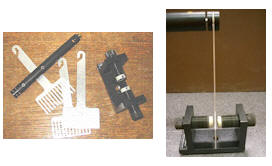
The videos show a pendulum made from an aluminum paddles. The paddle is
either a solid aluminum plate or it is slotted like a comb. The paddle swings
between the poles of a magnet. Video 1 shows how eddy currents can brake the
swing of the pendulum and video 2 shows how eddy currents can cause the moving
magnet to drag the paddle with it.
A powerful induction cannon can be made by placing a metal cylinder inside a
solenoid coil. The cylinder is forcefully expelled when solenoid current is
turned on rapidly. Why
might the cylinder get hot when the cannon is fired?
Discuss this with your fellow students in the discussion forum!
Use Faraday's and Lenz's laws to explain how this works.
Transformers
The function of a transformer is to change the voltage so that it suits the
needs of a particular application.
A prototype of a transformer has a primary and a secondary coils wound on
either side of an iron ring. If the current in the primary coil is changing, the
flux through the secondary coil changes and an emf is induced in the secondary
coil. The emf induced in the secondary coil is proportional to the number of
turns N2 of the secondary coil, since the number of turns determines
the total magnetic flux passing through this coil. The induced emf is also
proportional to the voltage V1 across the primary coil, since this
determines the magnitude of the primary current and its associated magnetic
field. The induced voltage is inversely proportional, however, to the number of
turns N1 of the primary coil. The relationship takes the form
V2/N2
= V1/N1.
The ratio of the number of turns on the two coils determines the ratio of the
voltages. Self-inductance is the reason that the emf induced in the secondary
coil is inversely proportional to the number of turns of the primary coil. If
the primary coil has more turns, it is harder to produce a rapid change in
current flowing through it, because of the back emf produced by self-induction. This effect limits the current and therefore the magnitude of the magnetic field
produced by the primary coil, which in turn limits the magnetic flux passing
through the secondary coil.
Problem:
You need 12 V to run an electric train, but the outlet voltage is 120 V. What is the ratio of the number of turns on the primary coil to the number
of turns on the secondary coil of the transformer you are using?
Solution:
Reasoning:
For a transformer V2/N2 = V1/N1.
Details of the calculation: N1/N2 = V1/V2. You need a transformer with ten
times as many turns on the primary coil as on the secondary coil.
A cathode-ray tube in an old-fashioned television set needs a much higher voltage than
120 V. The transformer must have many more turns on the secondary than on the
primary coil.
If the output voltage is higher than the input voltage, are we somehow
getting more power out of the transformer than we put in?
The answer, of course, is no. The power delivered to the secondary circuit is
always less than, or at best equal to the power provided to the primary coil. Since electrical power can be expressed as the product of the voltage times the
current, conservation of energy provides a second relationship useful for
analyzing transformer.
V2I2 ≤ V1I1.
A high output voltage is associated with a low output current. The output
power does not exceed the input power. If the voltage is stepped down, then the
secondary current can be larger than the primary current.
The videos show the iron core of a coil connected to an AC power supply. When
the power is on, the magnetic flux through the core is changing with a frequency
of 60 Hz. Video 1 shows an aluminum ring placed over the iron core. The flux
through the ring is changing with a frequency of 60 Hz and eddy currents are
induce in the ring. The magnetic field due to these eddy currents opposes the
flux changes that produced the currents, and the disk is repelled. Video 2 shows
a loop of copper wire in series with a light bulb places over the iron core. The
eddy currents flowing through the circuit of copper wire and bulb cause the bulb
to glow.
High voltages are desirable for long distance transmission of electric power. The higher the voltage, the lower is the current. Since the power dissipated in
the wires in the form of heat is P = I2R, less energy is wasted when a smaller current flows. Transmission voltages can be as high as 230 kV. Transformers at electrical
substations reduce these voltages to 7200 volts for distribution into cities. Transformers on utility poles or partially underground reduce this voltage 220 V. This AC voltage is split inside a building to yield 110 V at most outlets. The
full 220 V are available for stoves, dryers, and electric heaters.
Problem:
The charger for a cell phone contains a transformer that reduces 120 V AC to
5 V AC to charge the 3.7 V battery. (It also contains diodes to change the 5 V
AC to 5 V DC.) Suppose the secondary coil contains 30 turns and the charger
supplies 700 mA. Calculate
(a) the number of turns in the primary coil,
(b) the average current in the primary, and
(c) the power transformed.
Solution:
Reasoning:
For a transformer V2/N2 = V1/N1,
V2I2 = V1I1.
Details of the calculation:
(a) N1/N2 = V1/V2. N1
= N2V1/V2 = 30*120/5 = 720. The primary coil has 720 turns.
(b) V2I2 = V1I1
if power loss is negligible. I1 = V2I2/V1
= 5*0.7/120 A = 29 mA. The average current in the primary is 29 mA. (c) P = V2I2 = V1I1
is the average power transformed. P = 5 V*0.7 A = 3.5 W.
 The magnetic flux through an area can change because the field strength is
changing, or because the direction of the field is changing. Rotating a
permanent magnet in front of a wire loop, or rotating a wire loop in front of a
permanent magnet will result in a change of the magnetic flux through the loop. This change in flux produces an emf and a current will start flowing in the loop. We have an electric generator. The basic
function of a generator is to convert mechanical energy into electrical energy.
A simple electric generator is shown in the figure on the right.
The magnetic flux through an area can change because the field strength is
changing, or because the direction of the field is changing. Rotating a
permanent magnet in front of a wire loop, or rotating a wire loop in front of a
permanent magnet will result in a change of the magnetic flux through the loop. This change in flux produces an emf and a current will start flowing in the loop. We have an electric generator. The basic
function of a generator is to convert mechanical energy into electrical energy.
A simple electric generator is shown in the figure on the right. The figure on
the right shows plots of the continuously varying magnetic flux and
the induced emf versus time. By Faraday's law, the magnitude of the induced emf
is equal to the rate of change of magnetic flux, so its maximum values occurs
when the flux curve has its greatest slope. The induced emf goes through zero
when the flux curve has zero slope. We observe a 90o phase shift
between flux and induced emf. If the coil of the generator is part of a closed circuit, and a current flows
in the circuit, the coil becomes a magnetic dipole with dipole moment
m = IAn in a magnetic field. A torque
τ = μ × B
is trying to align this dipole with the magnetic field. The coil has to be
turned, and mechanical work has to be done against this torque. The lower the
resistance of the circuit, the more current flows and the more mechanical work
has to be done. The rate at which mechanical work has to be done is equal to the
power dissipated by the circuit.
The figure on
the right shows plots of the continuously varying magnetic flux and
the induced emf versus time. By Faraday's law, the magnitude of the induced emf
is equal to the rate of change of magnetic flux, so its maximum values occurs
when the flux curve has its greatest slope. The induced emf goes through zero
when the flux curve has zero slope. We observe a 90o phase shift
between flux and induced emf. If the coil of the generator is part of a closed circuit, and a current flows
in the circuit, the coil becomes a magnetic dipole with dipole moment
m = IAn in a magnetic field. A torque
τ = μ × B
is trying to align this dipole with the magnetic field. The coil has to be
turned, and mechanical work has to be done against this torque. The lower the
resistance of the circuit, the more current flows and the more mechanical work
has to be done. The rate at which mechanical work has to be done is equal to the
power dissipated by the circuit. Eddy currents are currents
circulating in a conductor in response to a changing magnetic field. The
circulating currents produce a magnetic field opposing the change in flux. Eddy
currents transform ordered energy, such as kinetic energy, into thermal energy. In most cases this is undesirable. There are, however, some practical
applications, such as the
magnetic breaks
of some trains. Consider some section of a moving metal wheel. As this section
moves through the magnetic field from an electromagnet, the flux through the
section first increases and then decreases. The changing flux generates eddy
currents in this section of the wheel. The magnetic interaction between the
applied field and the field produced by the eddy currents produces a magnetic
drag and slows down the wheel.
Eddy currents are currents
circulating in a conductor in response to a changing magnetic field. The
circulating currents produce a magnetic field opposing the change in flux. Eddy
currents transform ordered energy, such as kinetic energy, into thermal energy. In most cases this is undesirable. There are, however, some practical
applications, such as the
magnetic breaks
of some trains. Consider some section of a moving metal wheel. As this section
moves through the magnetic field from an electromagnet, the flux through the
section first increases and then decreases. The changing flux generates eddy
currents in this section of the wheel. The magnetic interaction between the
applied field and the field produced by the eddy currents produces a magnetic
drag and slows down the wheel.
 Clever designs can exploit eddy currents.