
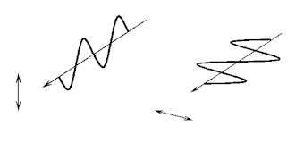
Polarization is a phenomenon peculiar to transverse waves. Longitudinal waves such as sound cannot be polarized. Light and other electromagnetic waves are transverse waves made up of mutually perpendicular, fluctuating electric and magnetic fields. In the diagram below an EM wave is propagating in the x-direction, the electric field oscillates in the xy-plane, and the magnetic field oscillates in the xz-plane. A line traces out the electric field vector as the wave propagates.

An unpolarized electromagnetic wave traveling in the x-direction is a superposition of many waves. For each of these waves the electric field vector is perpendicular to the x-axis, but the angle it makes with the y-axis is different for different waves. For unpolarized light traveling in the x-direction Ey and Ez are randomly varying on a timescale that is much shorter than that needed for observation.
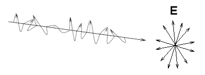
For a linearly polarized electromagnetic wave traveling in the x-direction, the angle the electric field makes with the y-axis is unique.
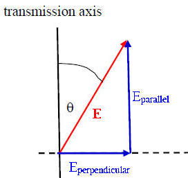 An ideal polarizer is a material that passes only EM waves for which the electric
field vector is parallel to its transmission axis. The electric field is a
vector and can be written in terms of the components parallel and perpendicular
to the polarizer's transmission axis.
E = Eparallel
+ Eperpendicular.
An ideal polarizer passes Eparallel
and absorbs Eperpendicular.
If
E0 is the incident
field vector and the angle between E0 and the transmission
axis is θ, then the magnitude of transmitted field
vector is E0 cosθ and its direction is the
direction of the transmission axis. The intensity I of an electromagnetic wave
is proportional to the square of the magnitude of the electric field vector. We
therefore have
Itransmitted = I0 cos2θ.
This is called the law of Malus. If θ = 90o the transmitted intensity is zero.
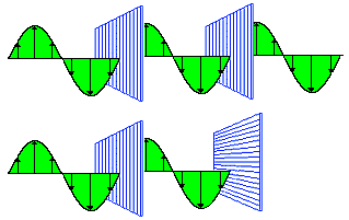
When unpolarized
light passes through a polarizer, the intensity is reduced by a factor of ½.
The average of cos2θ, averages over all angles θ is ½.
Itransmitted = I0<cos2θ>all angles =
½I0.
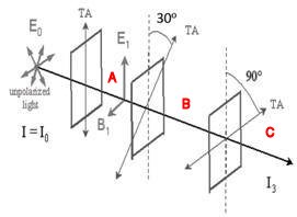 A beam of unpolarized light of intensity I0 passes
through a series of ideal polarizing filters with their transmission
axis turned to various angles, as shown in the figure.
(a) What is the light intensity (in terms of I0) in
regions A, B, and C?
(b) If we remove the middle filter, what will be the light intensity at
point C?
Solution:
There are different polarization mechanisms. The most common method of producing polarized light is to use polaroid material, made from chains of organic molecules, which are anisotropic in shape. Light transmitted is linearly polarized perpendicular to the direction of the chains. The transmission axis is perpendicular to the chains.
A polarizer produces linearly polarized light. It is often convenient to orient the transmission axis of a polarizer vertically or horizontally to produce light with vertical or horizontal linear polarization.
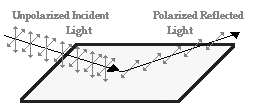 When unpolarized light is incident on a boundary
between two dielectric surfaces, for example on an air-water boundary, then the
reflected and transmitted components are partially polarized. The
reflected wave is 100% linearly polarized when the incident angle is equal to an
angle called the
Brewster angle.
For water this angle is is ~53o with respect to
the normal or 37o with respect to the water surface.
For are
considerable angular range around the Brewster angle the reflected light is
highly polarized in the horizontal direction.
 When
the sun is at a low angle in the sky, the sunlight reflecting off the surface of
water is nearly 100% horizontally polarized because the angle of incidence is
close to the Brewster angle.
Glare-reducing
sunglasses are coated with a polarizer with a vertical transmission axis and
therefore block the reflected light.
External link:
Polarization of light (Youtube)
External link:
Polarization and reflection (Youtube)
The way light is transmitted through some materials depends on its polarization.
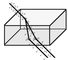 Certain birefringent crystalline substances bend light trough an
angle that depends upon the state of incident polarization. The have an optic
axis. Unpolarized light entering a birefringent crystal not along the
optic axis of the crystal is split into beams which are bend by different
amounts.

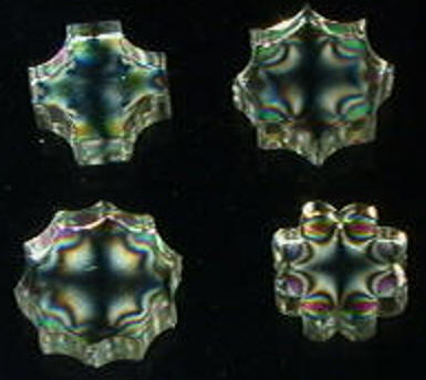
Some materials turn birefringent when stressed. By placing transparent materials between two polarizers, we can perform stress analysis tests.
Optically active or circular birefringent materials rotate the direction of polarization of linearly polarized light. The amount of rotation depends on the wavelength of the light. Sugar molecules have a handedness (chirality) and in solution are optically active. If we polarize white light and pass it through sugar syrup, the direction of polarization of the light emerging from the syrup will be different for the different color components. If the light then passes through a second polarizer, its color changes with the orientation of the transmission axis of this polarizer.

Sugar syrup between crossed polarizers
with different relative orientations