 All waves interfere. In regions where two light waves overlap, their electric
field vectors add. Light waves with the same polarization can interfere
constructively or destructively.
Waves that interfere constructively are in phase, waves that interfere
destructively are 180o out of phase. For the interference to
not change with time, the waves have to maintain
their phase relationship, they have to be coherent.
All waves interfere. In regions where two light waves overlap, their electric
field vectors add. Light waves with the same polarization can interfere
constructively or destructively.
Waves that interfere constructively are in phase, waves that interfere
destructively are 180o out of phase. For the interference to
not change with time, the waves have to maintain
their phase relationship, they have to be coherent.
How do we make sure two interfering waves have the same polarization? We
split one wave into two waves.
One way to split one wave onto two waves is called division of wave front.
We pass the same wave front through two closely spaced slits.
The double slit
 If light is incident onto an obstacle which contains
two very small slits a distance d apart, then the wavelets emanating
from each slit will interfere behind the obstacle. Waves passing
through each slit are diffracted and spread out. At angles where the
single slit diffraction pattern produces nonzero intensity, the waves
from the two slits can now constructively or destructively interfere.
If light is incident onto an obstacle which contains
two very small slits a distance d apart, then the wavelets emanating
from each slit will interfere behind the obstacle. Waves passing
through each slit are diffracted and spread out. At angles where the
single slit diffraction pattern produces nonzero intensity, the waves
from the two slits can now constructively or destructively interfere.
If we let the light fall onto a screen behind the obstacle, we will
observe a pattern of bright and dark stripes on the screen, in the
region where with a single slit we only observe a diffraction maximum. This pattern of
bright and dark lines is known as an interference
fringe pattern. The bright lines indicate
constructive interference and the dark lines indicate destructive
interference.
The bright fringe in the middle of the diagram on the right is caused
by constructive interference of the light from the two slits traveling
the same distance to the screen. It is known as the
zero-order fringe.
Crest meets crest and trough meets trough. The dark fringes on either
side of the zero-order fringe are caused by destructive interference.
Light from one slit travels a distance that is ½ wavelength longer
than the distance traveled by light from the other slit. Crests
meet troughs at these locations. The dark fringes are followed by
the first-order fringes,
one on each side of the zero-order fringe. Light from one slit
travels a distance that is one wavelength longer than the distance
traveled by light from the other slit to reach these positions. Crest
again meets crest.
Note: We need single-slit diffraction to
observe double-slit interference. Without the spreading, waves
light waves passing through different slits would not meet and therefore
could not interfere.
 The diagram on the right shows the geometry for the fringe pattern. If
light with wavelength λ passes through two slits separated by a distance
d, we will observe constructively interference at certain angles. These
angles are found by applying the condition for constructive
interference, which is
The diagram on the right shows the geometry for the fringe pattern. If
light with wavelength λ passes through two slits separated by a distance
d, we will observe constructively interference at certain angles. These
angles are found by applying the condition for constructive
interference, which is
d sinθ = mλ, m = 0, 1, 2, ... .
The distances from the two slits to the screen differ by an integer number of wavelengths.
Crest meets crest.
The angles at which dark fringes occur can be found be applying the condition for
destructive interference, which is
d sinθ = (m+½)λ, m = 0, 1, 2, ... .
The distances from the two slits to the screen differ by an integer number of wavelengths + ½
wavelength. Crest meets trough.
If the interference pattern is viewed on a screen a distance L from
the slits, then the wavelength can be found from the spacing of the fringes.
We have sinθ = z/(L2 + z2)½ and λ = zd/(m(L2 + z2)½), where z is the distance from the center of the interference pattern
to the mth bright line in the pattern.
If L >> z then (L2 + z2)½ ~ L and
we can write
λ = zd/(mL).
Diffraction and interference are phenomena which are observed with all waves.
Link: Observe single and double slit diffraction with water waves
AI Study Tip:
Example prompt: I am studying Module 8 (Wave Optics) in an
algebra-based introductory physics course. Act as a physics tutor. Explain the
primary conceptual differences between a single-slit diffraction pattern and a
double-slit interference pattern. Use a real-world analogy that doesn't rely on
calculus, and explain why the intensity profiles of the fringes look different
for each.
Diffraction gratings
We have seen that diffraction patterns can be produced
by a single slit or by two slits. When
light encounters an entire array of identical, equally-spaced slits,
called a diffraction grating, the bright fringes, which come
from constructive interference of the light waves from different slits,
are found at the same angles they are found if there are only two slits.
But the pattern is much sharper.
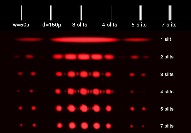
The figure below shows the
interference pattern for various numbers of slits. The width of all
slits is 50 micrometers and the spacing between all slits is 150
micrometers. The location of the maxima for two slits is also the
location of the maxima for multiple slits. The single slit
diffraction pattern
acts as an envelope for the multiple slit interference patterns.
Diffraction gratings contain a large number of parallel, closely spaced slits or grooves. They
produce interference maxima at angles θ given by
d sinθ = mλ. Because the spacing between the slits is
generally very small, the angles θ are generally quite large. We
cannot use the small angle approximation for relating wavelength and the
position of the maxima on a screen for gratings, but have to use
sinθ = z/(L2 + z2)½.
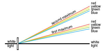
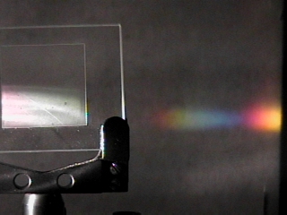
Diffraction gratings disperse white light into its component colors because different wavelengths produce bright fringes at
different angles.
d sinθ = mλ,
for a given m, bigger wavelength <==> bigger angle
The spectral pattern is repeated on either side of the main pattern.
These repetitions are called "higher order spectra". There are
often many of them, each one fainter than the previous one. If the
distance between slits is d, and the angle to a bright fringe of a
particular color is θ, the wavelength of the light can be calculated.
Please watch: Passing
Light Through Multiple Apertures - Exploring Wave Motion (YouTube)
Problem:
The first order bright line appears 0.25 cm from the center bright line when
a double slit grating is used. The distance between the slits is 0.5 mm and the
screen is 2.7 m from the grating. Find the wavelength.
Solution:
- Reasoning:
When light with wavelength λ passes through equally spaced slits separated
by a distance d, constructively interference occurs at angles θ given by d sinθ = mλ, m = 0, 1, 2, ... .
Here m = 1 and we are asked to solve this equation for λ.
- Details of the calculation:
z = 0.25 cm = 2.5*10-3 m.
L = 2.7 m.
d = 0.5 mm = 5*10-4
m.
L >> z, therefore sinθ ~ z/L and λ = zd/(mL).
λ = (2.5*10-3
m)(5*10-4 m)/(2.7 m).
λ = 4.63*10-7 m = 463 nm.
Problem:
A diffraction grating has 420 lines per mm. The grating is used to observe
normally incident light with a wavelength of 440 nm. The grating is placed 1.3 m from a screen. Where
on the screen will the first order bright line appear?
Solution:
- Reasoning:
When light with wavelength λ passes through equally spaced slits separated
by a distance d, constructively interference occurs at angles θ given by d sinθ = mλ, m = 0, 1, 2, ... .
Here m = 1 and we are asked to solve this equation for sinθ and then
for z.
- Details of the calculation:
d sinθ = λ.
d = (1/420) mm = 2.38*10-3
mm = 2.38*10-6 m.
λ = 440 nm = 4.40*10-7 m.
L = 1.3 m
= distance to the screen.
sinθ = λ/d = 10.65o.
z = L tanθ = 24.5 cm = distance from the central maximum.
Problem:
A monochromatic wave of wavelength λ illuminates an opaque
mask with two slits as shown in the figure. The diffraction pattern is recorded
on a screen a distance L from the mask. You may assume that λ << d. D << L.
(a) What is the distance Λ between adjacent interference fringes observed on the
screen?
(b) What is the width Δx of the central lobe of the interference pattern on the
screen?
Solution:
- Reasoning:
The distance Λ between adjacent interference fringes is the distance between
adjacent maxima of the double slit interference pattern.
The width Δx of the central lobe of the interference pattern equals twice
the distance from the central maximum to the first minimum of the single
slit interference pattern.
- Details of the calculation:
(a) For the distance between adjacent maxima of the double slit pattern we
have Dsinθ = λ.
Here sinθ ≈ θ ≈ Λ/L. So Λ = λL/D.
(b) For the distance from the central maximum to the first minimum of the
single slit interference pattern we have dsinθ = λ.
Here sinθ ≈ θ ≈ Δx /(2L). So Δx = λ2L/d.
Embedded Question 1
- What is the difference between diffraction and interference?
- Compare the formulas for the bright maxima and dark minima in the
diffraction and interference patterns.
When you solve problems using these formulas, what do you have to be careful
about?
Discuss these questions with your fellow students in the discussion forum!
Diffraction and interference patterns can be observed when light passes through a set of
regularly spaced slits. For diffraction to produce an observable
pattern, the spacing of the slits must be comparable to the wavelength of the
radiation. Visible light has a wavelength range from ~400 nm to ~700 nm.
A typical diffraction grating for visible light with 300 grooves per mm has a
slit spacing of (1/300)mm ~ 3 μm = 3000 nm.
This spacing is approximately 4 to 8 times larger than the wavelengths of visible light and
produces an easily observable pattern.
The wavelengths of x-rays lie in the 1 nm to 1 pm range. A typical
diffraction grating will not produce an observable pattern. But the
wavelengths of x-rays are comparable to the spacing of atoms in common crystals,
and material with a regularly spaced grid of atoms can diffract x-rays and
produce diffraction patterns that can be captured on photographic film.
Interference patterns are only observed if the interfering light from the
various sources is coherent, i.e.
if the phase difference between the sources is constant. Splitting the light
from a single source into various beams is one way to produce coherent sources.
Light from two different light bulbs is incoherent and will not produce an
interference pattern. Lasers are sources of monochromatic (single
wavelength), coherent light. Two lasers can maintain a constant phase
difference between each other for relatively long time intervals.
If you miss having regular lectures, consider these video lectures
Lecture 33:
Double-Slit Interference and Interferometers
Lecture 34:
Gratings and Resolving Power