Refraction and reflection
In this lab you will explore the behavior of light at the boundary
between two transparent media with different indices of refraction. A
fraction of the incident intensity will be reflected, and the rest of the light
will be transmitted. The direction of propagation of the reflected and
transmitted light is given by the laws of reflection and refraction.
- Law of reflection: θi = θr
- Snell's law or law of refraction: nisinθi = ntsinθt.
 How much of the light is reflected and how much is transmitted?
The reflectance R is the ratio of the reflected
flux to the incident flux, and the transmittance
T is the ratio of the transmitted flux to the incident flux.
Energy conservation requires that R + T = 1 (if there is no absorption).
R and T depend on the indices of refraction of the two media n1
and n2, the angle of incidence θi,
and the polarization of the incident light.
We distinguish between p-polarization and s-polarization.
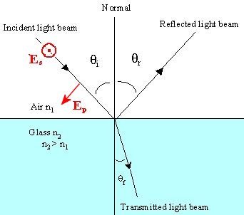
Consider, for example, an air-glass interface as shown. The plane of incidence contains the normal to the boundary and the
incident ray. The electric field vector E of the incident
wave is perpendicular to the direction of propagation and can have a component in the plane of incidence,
Ep,
and a component perpendicular to the plane of incidence Es.
We have E = Ep+
Es.
 The reflectance R depends of the polarization and is given for p-polarization by
Rp = ((tan(θi - θt)/tan(θi
+ θt))2,
and for s-polarization by
Rs = ((sin(θi - θt)/sin(θi
+ θt))2.
If θ1 + θ2 = π/2, then tan(θ1
+ θ2) = infinite and Rp = 0. If light is reflected, it
will have s-polarization. The incident angle at which this happens
is called the Brewster angle θB. We then have
n1sinθB = n2sin((π/2) -θB) = n2cosθB.
tanθB = n2/n1.
Explore using this spreadsheet.
Vary n1 and n2 and observe the changes.
Open a Microsoft Word document to keep a log of your procedures,
results and discussions. This log will become your lab report. Address the
points highlighted in blue. Answer all questions.
Exploration
Use an on-line simulation from the University of Colorado PhET group to explore the bending of light.
Link to the simulation:
https://phet.colorado.edu/en/simulations/bending-light
Explore the interface!
- Tools and objects can be dragged out of the tool box and then returned.
- The objects in the Prism tab can be rotated by dragging the handle.
- In the Prism Break tab, the protractor rotates and the laser translates.
- All the tools work in both Ray and Wave mode, but some are easier to use
in Wave mode because the region where the tool can read is larger.
(a) Click on either the Intro or More Tools tab. Let red light
move from air into water. (Make sure you select water if you click the More
Tools tab.)
For incident angles θi from to zero 80o in 10 degree
steps measure the angle of refraction θt and the reflected
intensity or reflectance R.
Download this spreadsheet and enter your measured
values on sheet 1.
- Plot R versus theta (deg). Paste your graph into your log. Compare to the graph above.
- Discuss your result.
- Is the laser light p-polarized, s-polarized, or unpolarized.
- What do your results suggest?
- Calculate sinθi and sinθt. Remember that Excel functions require the angles to be in radians.
The first row if the spreadsheet already contains the formulas.
- Plot sinθi versus sinθt.
- What does the plot look like?
- Use the trendline to find the slope. Paste the graph with trendline into your log.
- What value do you obtain for the slope?
- Given Snell's law, what value do you expect
for the slope? Discuss!
(b) Design experiments to determine the index of refraction of mystery
materials A and B.
- Describe your procedure and discuss why you
decided to proceed this way. What are your results for nA
and nB?
(c) Design and describe a setup that has the
refracted ray bend away from the normal?
- Paste a screen shot of your setup into your log.
(d) Click on the prism tab. Use red light with a wavelength
of 650 nm. Try to arrange various prisms in such a way, so that the laser
beam after total internal reflections moves parallel to the incident beam but in
the opposite direction. Try to use as few pieces as possible.
- Paste a screen shot of your design into your log.
(e) Now switch to white light and experiment with various prisms to
answer the following questions.
- Are the reflection and refraction of light color-dependent? How can you tell?
(Make sure you also show reflection by clicking the checkbox.)
- Which shapes split the white light into different colors the best? Did you find a set-up that demonstrates this well?
- Try to arrange a situation so that the light light forms a rainbow. What shape did you choose?
Experiment:
In this experiment you will trace the path of a light ray through a block of
glass and measure the index of refraction of the glass. For an air-glass
boundary we can set the index of refraction of air equal to one. Snell's
law therefore yields for the index of refraction of the glass
nglass = sinθair/sinθglass.
It is easy to measure θair, but not θglass inside the
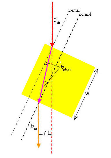
glass. But when a light ray enters square block of glass from air making a
nonzero angle θair with the normal to the interface, the ray is bent
towards the normal as its enters and away from the normal as it leaves the glass
block. The emergent ray moves in the same direction as the incident ray,
but is displaced parallel to the incident ray. The parallel displacement d
depends on index of refraction nglass and the width w of the block.
By measuring the displacement d, we can determine nglass.
Procedure:
Click to open the
"optics lab"
simulation. It contains a laser, an optical breadboard
and several optical components. The components can be dragged to
different positions on the breadboard and the components can snap to the holes
on the breadboard which have a spacing of 1 unit = 2.5 cm. The screen is 4
units wide and 2 units high and the lines on the screen are spaced by ½ unit.
Clicking anywhere on the breadboard you can rotate and zoom the view.
When the simulation opens the laser beam passes through a glass block.
The dimensions of the glass block are
2.8 by 2.8 by 1.4 units.
- Drag the
glass block out of the way and position the screen so that the undeflected
beam hits the middle of the screen.
- Keep the
rotation angle of the glass block at 0o and drag the glass block
back into position so that the laser beam passes through the block and hits
the middle of the screen.
- Click
the "Rotate postholder" button and rotate the glass block until the laser
beam is displaced by d = 1/4 unit. Remember that the lines on the
screen are spaced by ½ unit. Decrease the beam radius to its minimum
value so that you can make a more precise measurement. You can also
drag the screen close to the glass block, and you can rotate an zoom the
view.
- Record the angle θair corresponding to d = 1/4 unit
in your spreadsheet on sheet 2.
- Repeat for d = ½ unit, 3/4 unit and 1 unit, for a total of 4
measurements.
Data Analysis:
Use your measurements to determine the index
of refraction nglass of the glass block.
 The expected displacement of a ray passing through the glass block is d. From the figure on the right we see that
d/L = sin(θair - θglass),
w/L = cos(θglass).
This can be rewritten as
d = wsin(θair - θglass)/cos(θglass),
and applying Snell's law and trigonometric relations
d = w sinθair[1 - cosθair/(nglass2
- sin2θair)½].
This equation can be solved for nglass.
nglass2 = cos2θair/(1 -
d/(w sinθair))2 + sin2θair.
Use your spreadsheet to calculate nglass for each of your 4
measurements. Paste your spreadsheet table into your log.
- Do your measurements agree with each other within
reasonable uncertainty, given how you performed your measurements.
- Do you suspect some of the measurements to be more accurate than others?
If yes, why?
- From your measurements, what do you conclude is the index of refraction n +
Δn of the glass block?
Convert your log into a lab report.
See the grading scheme for all lab
reports.
Name:
E-mail address:
Laboratory 10 Report
- In one or two sentences, state the goal of this lab.
- Make sure you completed the entire lab and answered all parts. Make
sure you show your work and inserted and properly labeled relevant tables
and plots.
- Add a reflection at the end of your report in a short essay format.
Save your Word document (your name_lab10.docx), go to Canvas, Assignments, Lab
10, and submit your document.