Physics Laboratory 7
Ampere's law and the e/m experiment
Moving charged particles produce magnetic fields and are acted on by magnetic
fields. Currents are moving charges and therefore they produce and are
acted on by magnetic fields. Permanent magnets are the result of
"magnetization currents" flowing inside the material.
In experiment 1 of
this lab you will simulate using a giant magnetoresistive (GMR) sensor to measure the
strength of the magnetic field B produced by a current flowing in a circuit.
One section of the circuit is a long, straight wire. You will measure the
strength of the magnetic field near the middle of this wire as a function of the
distance from the wire, for distances much smaller than the length of the wire.
You will also use Ampere's law to calculate the magnetic field strength B
produced by a current flowing in an infinitely-long, straight wire (with the
rest of the circuit at infinity). You will
compare the results of your measurements with the results of
your calculations.
In experiment 2 of this lab you will observe the deflection of electrons in a
magnetic field and use this deflection to determine the electron's charge to
mass ratio.
Open a Microsoft Word document to keep a log of your experimental procedures,
results and discussions. This log will become your lab report. Address the
points highlighted in blue. Answer all questions.
Experiment 1
You will measure the magnetic field strength near a current-carrying long
straight wire, as a function of the perpendicular distance from the center of
the wire. You will verify that close to the wire and near its center
Ampere's law can be used to make reasonable predictions, even if the wire is not
infinitely long. You will learn about
giant magnetoresistive sensors.
Theory
 Ampere's law applied to an infinitely-long wire predicts a magnetic field of strength
B = μ0I/(2πr) a radial distance r from the wire. The field B is tangential to a circle of radius
r centered on the wire.
Ampere's law applied to an infinitely-long wire predicts a magnetic field of strength
B = μ0I/(2πr) a radial distance r from the wire. The field B is tangential to a circle of radius
r centered on the wire.
We therefore have (B/I) = (μ0/(2π))(1/r).
B/I is proportional to 1/r, and when plotted versus 1/r will yield a straight
line with slope μ0/(2π).
Method
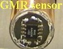
 In this experiment you will use
a GMR sensor to measure magnetic field strength.
In a GMR sensor, the resistance of two thin ferromagnetic layers, separated by a thin,
nonmagnetic conducting layer is altered by changing the magnetic moments of the
ferromagnetic layers from parallel to anti-parallel or vice versa.
In this experiment you will use
a GMR sensor to measure magnetic field strength.
In a GMR sensor, the resistance of two thin ferromagnetic layers, separated by a thin,
nonmagnetic conducting layer is altered by changing the magnetic moments of the
ferromagnetic layers from parallel to anti-parallel or vice versa.
Layers with parallel magnetic moments have lower resistance than layers with
anti-parallel magnetic moments. The layers are typically less than 10 nm thick.
They are sputtered onto semiconductor wafers and they are patterned into narrow stripes.
A very small current flowing through the conducting layer across the stripes rotates the magnetic
layers into anti-parallel, high-resistance alignment. An external magnetic field applied
perpendicular to the direction of current flow and parallel to the stripes can overcome
the field produced by the current and rotate the magnetic moments of both layers parallel
to the field. The amount of current needed to destroy the alignment caused by the external
field is a measure of the magnetic field strength.
Smart sensors with sensing elements and associated electronics on the same chip can be
bought. These sensors have a sensitive axis (along the stripes) and can directly detect
the component of the magnetic field along this axis. The diagram below shows two GMR
sensors positioned to measure the magnetic field of a bar magnet. The sensitive axes are
indicated and the component of the field along the sensitive axes for the two sensors is
plotted.
Apparatus
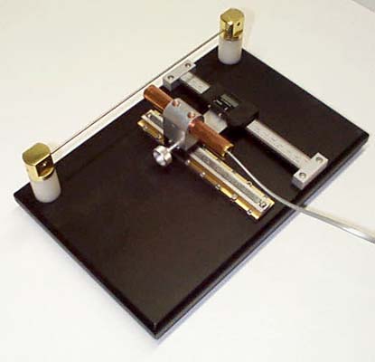
 The Ampere's Law apparatus is shown in the figure above. It is used to measure B as a
function of the radial distance r from a wire, for r much
smaller than the length of the wire. For this apparatus r is the distance
between the center of the wire and the point at where the GMR sensor is located
beneath the surface of its mounting package.
The Ampere's Law apparatus is shown in the figure above. It is used to measure B as a
function of the radial distance r from a wire, for r much
smaller than the length of the wire. For this apparatus r is the distance
between the center of the wire and the point at where the GMR sensor is located
beneath the surface of its mounting package.
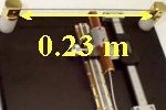 The straight wire is 0.23 m long,
and we measure the strength of the magnetic field near the middle of this wire
as a function of the distance from the wire for r = 1.68 mm to 11.68 mm.
The straight wire is 0.23 m long,
and we measure the strength of the magnetic field near the middle of this wire
as a function of the distance from the wire for r = 1.68 mm to 11.68 mm.
The distance r is determined with a digital scale to
a precision of 0.1 mm. Initially the top surface of the IC mounting package is positioned
so that it touches the wire and the digital scale is zeroed. At this position, r = r0 = 1.68 mm. r0 is the sum of the radius
of the wire (1.18 mm) and the sensor depth (0.5 mm). r0 must be added to all subsequent
readings of the digital scale.
To pass a current through the wire, it must
become part of a larger circuit that includes a power supply. The distance
from the sensor to the connecting wires is much larger than r, and so the
magnetic field produced by the connecting wires contributes very little to the
measured magnetic field strength.
The magnetic field produced
by the wire encircles the wire and its direction at the position of the sensor is
perpendicular to the base plate. The sensor is mounted so that its sensitive axis is also
perpendicular to the base plate. The output voltage of the sensor V is directly
proportional to the magnetic field strength B to be measured if an appropriate
offset voltage has been subtracted.
The offset voltage is partly due to the earth magnetic field and partly due to sensor electronic.
It must be determined before each measurement by reading the voltage when no current is
flowing in the wire. The current is turned on and off with a switch.
Open a Microsoft Word document and keep a log of your activities. Answer all the questions in blue font.
Procedure
Start the experiment by clicking the link.
http://labman.phys.utk.edu/ampere/
- The current flowing in the wire is determined with a digital ammeter build into the
power supply. The power supply is set to current mode, and when turned on delivers a current of 10 A.
- The output voltage of the sensor is determined with a digital voltmeter.
Open a new Excel spreadsheet and create a data table with columns as
shown below. (Make sure you enter the distance d in m, not mm.)
| r0 |
d |
V0 |
V |
I |
1/r |
ΔV |
k |
B/I |
| 0.00168 |
|
|
|
|
|
|
|
|
| 0.00168 |
|
|
|
|
|
|
|
|
The labels denote the following quantities.
| r0 |
1.68 mm = 1.68*10-3 m |
| d |
reading of the digital scale
(meter) |
| V0 |
positive or negative offset Voltage with no current flowing (Volt) |
| V |
output voltage with current flowing
(Volt) |
| I |
current flowing in wire when switch is closed
(Amp) |
| 1/r |
1/(r0 + d) |
| ΔV |
(V - V0) |
| k |
calibration constant (see apparatus label ~10-4 T/V) |
| B/I |
B/I = kΔV/I with I
= 10 A. |
Start taking data. Click the switch to turn the power supply on or off.
As a function of r measure V0 (no current) and V (current) in quick succession, so
that the offset voltage has very little time to change.
Record d (in units of m), V0, V, and I in your data table.
Take data in 0.2 mm intervals for scale readings from 0 mm to 10 mm.
Data analysis
- Compute the remaining columns in your data table.
- Produce a graph of B/I versus 1/r.
- Use the trendline to fit your data to a straight
line and find the slope and the intercept of this straight line. Make sure the fitted values are displayed
with at least 3 significant digits.
- Insert the first few lines of your table and your graph into your Word document.
- Ampere's law predicts a slope of μ0/(2π) = 2*10-7N/A2.
Compare your measured value with the accepted
value. Find the percentage difference.
Note: Because B is inversely proportional to r, the field strength is largest
and changes most rapidly as a function of r close to the wire. As a result the
measurements near the wire dominate the analysis.
- Over the range of distance from this finite-sized wire measured, do you feel comfortable using
Ampere's law to predict the magnetic field strength?
Activity 1
Magnetic fields exert forces on other moving charge. The force a magnetic field exerts on a charge q, moving
with velocity v, is called the
Lorentz force.
It is given by F = qv × B.
Assume a charged particle is
moving with velocity v through a region with magnetic field
B.
Predict the direction of the magnetic force for each
situation below. Assume that the particle is positively charged.
Record your predictions in your log.
(a) (b)
(b)
(c) (d)
(d)
Experiment 2
Mass spectrometry has become an important
measurement tool in clinical chemistry, microbiology, toxicology and in the
pharmaceutical world. A mass spectrometer deflects ionized and accelerated
molecular fragments using a magnetic field and sorts them according to their
charge to mass ratio. For this exercise you will use
an e/m apparatus like a mass spectrometer to determine the electron's
charge to mass ratio, e/m, by measuring the radius of curvature of an electron's
path in a uniform magnetic field of known strength.
Open the "Electron
motion in a magnetic field" simulation.
Click Instructions in the upper left corner and read the instructions page
carefully.
Procedure
- Turn the power supply on and wait for the electron beam path to become
visible. The initial acceleration voltage is 200 V.
- Increase the coil current until the electrons move in a circle of radius
r = 5 cm or diameter 10 cm. (Take some time to adjust the current
carefully.)
- Paste the table below into an Excel spreadsheet and enter your measured
value for the coil current into the table.
- Repeat for the other accelerating voltages in the table.
- Let Excel calculate the remaining columns in the table.
- Produce a graph of 2V versus (Br)2 and label the axes.
Accelerating
voltage
(V) |
Current
to coils
I (A) |
Magnetic field B
=
(7.56*10-4T/A)*I |
Radius of
circular path
r (m) |
(Br)2
(units: T2m2) |
2V
(units: J/C) |
|
200 |
|
|
0.05 |
|
|
|
220 |
|
|
0.05 |
|
|
|
240 |
|
|
0.05 |
|
|
|
260 |
|
|
0.05 |
|
|
|
280 |
|
|
0.05 |
|
|
|
300 |
|
|
0.05 |
|
|
-
Insert your graph into your Word document.
-
What is the slope of your trendline? (Note: The
slope will have units (J/C)/(Tm)2 = C/kg.)
-
What is your measured value of e/m?
-
Calculate e/m from the
accepted values of the
electron's charge and mass. Does the value of e/m from your experiment agree
with the calculated value? Given your experimental procedure, how close do you
expect them to agree?
The black ring holding the e/m tube is designed so that the tube can be rotated
through 10 degrees. The tube can therefore be oriented so that the initial
electron velocity makes an angle from 0 - 10 degrees with the magnetic field from the
Helmholtz coils. Rotate the tube and study how the beam deflection is affected.
- Describe your observations as you rotate the tube.
- Describe what happens when you change the current to the Helmholtz
coils.
- Describe what happens when you change the accelerating voltage.
Convert your log into a lab report.
See the grading scheme for all lab
reports.
Name:
E-mail address:
Laboratory 7 Report
- In one or two sentences, state the goal of this lab.
- Make sure you completed the entire lab and answered all parts. Make
sure you show your work and inserted and properly labeled relevant tables
and plots.
- Add a reflection at the end of your report in a short essay format.
Save your Word document (your name_lab7.docx), go to Canvas, Assignments, Lab
7, and submit your document.