All waves diffract, if they pass through or around obstacles, and interfere, if two or more waves arrive at the same place at the same time. Light is an electromagnetic wave. When a monochromatic plane wave passes through a single slit of width w, we observe a Fraunhofer single slit diffraction pattern a large distance L >> w away from the slit. When the wave passes through multiple regularly-spaced slits with slit-spacing d, we observe a multiple-slit Fraunhofer interference pattern a large distance L >> d away from the slits.
In this lab you will use a simulation to observe a He-Ne laser beam (λ = 633 nm) to produce diffraction and interference pattern. You will use these patterns to measure the width of a single slit and a hair and the spacing of two slits.
Electromagnetic waves are transverse waves. Transverse waves can be polarized. In this lab you also will investigate various polarization effects.
Open a Microsoft Word document to keep a log of your procedures. This log will become your lab report. Address the points highlighted in blue. Answer all questions.
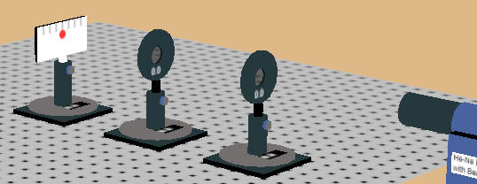
In the simulation a He-Ne laser beam (λ = 633 nm) produces Fraunhofer diffraction and
interference pattern that you can observe on a screen. A mouse is required
to interact with the simulation. It does not respond to touch. You can drag four
different slides into the the of the laser beam, and you can vary the slide to
screen distance. Clicking anywhere on the breadboard you can rotate and
zoom the view. The screen and the slides snap to the holes on the
breadboard which have a spacing of 1 unit = 2.5 cm. The screen is 4 units
wide and 2 units high and the lines on the screen are spaced by ½ unit.
Three of the slides block all the light except for a
single w = 20 μm wide slit or two or four w = 20 μm wide slits with slit
spacing d. From the observed patterns you can verify the slit width w and
determine the slit spacing d. The only thing blocking the laser light on a
fourth slide is a hair. You can measure the width of the hair using the
diffraction pattern produced by the laser light.
The lines on the slides are not drawn to scale. Their purpose is just to identify the slides. The most intense regions of the diffraction and interference patterns always have the same maximum color intensity allowed by the computer graphics. A realistic decrease in the color intensity with distance from the slit(s) would make the dimmer regions of the diffraction and interference patterns invisible at larger distances. That is a limitation of the computer graphics.
(a) Drag the single slit slide into into the path of the laser beam.
The slit width w is 20 μm. Observe the diffraction pattern.
Dark fringes in the diffraction pattern of a single slit are found at angles θ
for which w sinθ = mλ, m = 1, 2, ... .
To see a well-resolved pattern, use a large distance between the slit and the
screen.
(b) Drag the double slit slide into into the path of the laser beam. Each slit is w is 20 μm wide. Constructively interference at angles θ such that d sinθ = mλ, m = 0, 1, 2, ... .
(c) Drag the slide with four slits into into the path of the laser beam. Again each slit is w = 20 μm wide.
The dark fringes in the diffraction pattern of a single slit are found at angles θ for which w sinθ = mλ, where λ is the wavelength of the light and m is an integer, m = 1, 2, 3, ... .
 The intensity at the screen is proportional to the
square of the electric field amplitude.
The intensity at the screen is proportional to the
square of the electric field amplitude.
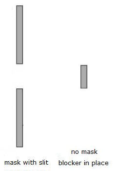
What if we remove the mask and only leave the blocker of width w? Using Huygens' principle we have
Emask with slit + Eblocker (no mask) = Enon-diffracted beam.
Here Emask with slit is the field
produced by sources at locations of the mask and Eblocker
(no mask) is the field produced by source at locations of the
blocker.
Therefore
Eblocker (no mask) = Enon-diffracted beam - Emask with slit.
For a laser beam the divergence angle θ0 is small, and for angles θ > θ0 we have
Eblocker (no mask) = - Emask with slit.
For angles θ > θ0 the average intensity, which is proportional to the square of the electric field, therefore is the same as that for the single slit. Dark fringes in the diffraction pattern are found at angles θ for which w sinθ = mλ.
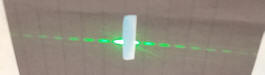
Drag the slide with the hair into into the path of the laser beam.
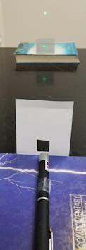
You can do this experiment at home and determine the thickness of your own hair if you have a laser pointer and you know the wavelength of the light. For most red laser pointers λ = 650 nm = 0.65 μm, and for most green laser pointers λ = 532 nm = 0.532 μm.
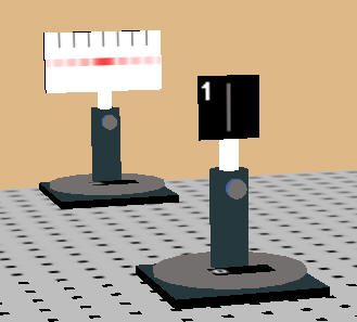
Open the polarization lab simulation. You are presented with a He-Ne laser, an optical breadboard and several optical components. The components can be dragged to different positions on the breadboard and the components can snap to the holes on the breadboard which have a spacing of 1 unit = 2.5 cm. The screen is 4 units wide and 2 units high and the lines on the screen are spaced by ½ unit. Clicking anywhere on the breadboard you can rotate and zoom the view. A transparent viewer can help you align the beam. All components can be translated and rotated, and the post holders can be raised and lowered with the mouse.
The He-Ne laser beam (λ = 633 nm) is unpolarized. You have 3 (ideal) linear polarizers and a power meter with a Bluetooth connection to a digital readout to monitor the beam intensity. You can also monitor the intensity of the laser beam on a screen (corrected for the average response of the human eye to light). The polarizers are mounted in a rotation stage. The transmission axis of the polarizers is horizontal when the rotation stage reads zero. You can explore what happens to the transmitted intensity if you rotate a third polarizer between two crossed polarizers and you can verify the Law of Malus. You can also reflect the laser beam off a glass slide and explore polarization by reflection. The back of the glass slide is painted black to absorb the transmitted portion of the beam. The slide is made of high-index of refraction glass, you can measure the index of refraction by finding the the Brewster angle.
Linear polarization: An ideal linear polarizer is a material that passes only light waves for which the electric field vector is parallel to its transmission axis. If E0 is the incident field vector and the angle between E0 and the transmission axis is θ, then the magnitude of transmitted field vector is E0 cosθ, and its direction is the direction of the transmission axis. The intensity I of an electromagnetic wave is proportional to the square of the magnitude of the electric field vector. We therefore have
Itransmitted = I0 cos2θ.
 |
 |
 |
| Polarizers with parallel transmission axes |
Polarizers with perpendicular transmission axes |
Polarizer 3 between polarizers 1 and 2. |
Spend a few minutes exploring what happens to the intensity of the beam spot on the screen as you pass the beam first through one and then through two polarizers. Observe the change in transmitted light intensity as either of the polarizers is rotated. This combination acts as a "light valve."
Briefly describe your observations.
Place a third polarizer between two crossed polarizers and rotate the transmission axis of the third polarizer while observing the intensity of the beam spot on the screen.
Briefly describe your observations.
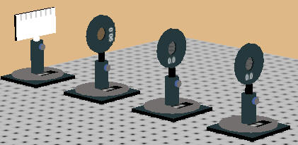
Experiment:
In this experiment you will use a linear polarizer to produces a polarized beam and then pass this beam through a second polarizer whose transmission axis makes an angle θ with respect to the transmission axis of the first one. You will check that Itransmitted = I0 cos2θ. This is called the Law of Malus.
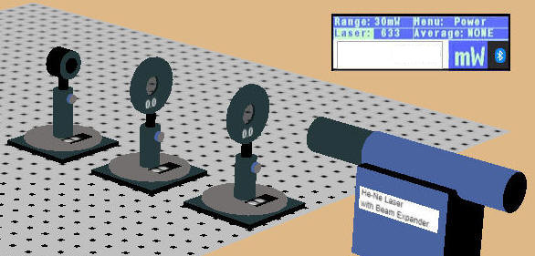
Use the setup shown in the picture above. It uses the power meter to monitor the beam intensity. You can increase the spacing between the components to make it easier to rotate the polarizers. Start with the transmission axes of both polarizers horizontal (zero degrees). If necessary, adjust the height of all components so that the beam falls onto the power meter and the meter reads 0.75 mW. (Note: The readout position is fixed, you cannot drag it around.)
After the laser light has passed through the polarizers, it is ~100% polarized along the horizontal direction, since the transmission axis of each polarizer is horizontal.
In Excel create a table. You can download the first row here.
| angle (deg) | angle (rad) | I (mW) | I0*cos2(angle) |
Convert your log into a lab report. See the grading scheme for all lab reports.
Name:
E-mail address:
Laboratory 9 Report
Save your Word document (your name_lab9.docx), go to Canvas, Assignments, Lab 9, and submit your document.