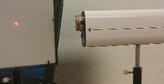
 Determine the focal length of a converging lens.
Do you wear glasses? Are you farsighted or nearsighted? Look through your or someone else's glasses as you move them towards
or away from a printed page. What do you see?
In the lab you will explore image formation. You
will determine the focal length of a thin lens and observe aberrations.
You will also examine what a camera records when it looks through a simple Keplerian
telescope and a simple compound microscope.
Open a Microsoft Word document to keep a log of your procedures, results and discussions. This log will become your lab report. Address the points highlighted in blue. Answer all questions.
Experiment 1
 Determine the focal length of a converging lens.
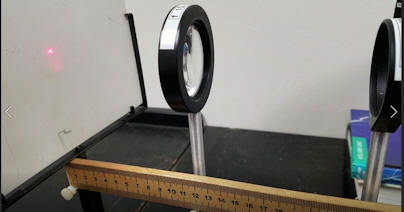 A converging lens and a mirror are also mounted on the optical rail. A
meter stick is used to determine the positions of the components on the rail.
The screen position is at 0 cm.
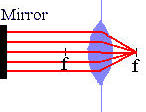
Observe coma.
Watch the video clip in full-screen mode. Describe what happens to the reflected spot. You should observe a lens aberration called "coma". It is observed when the light rays make large angles with the symmetry axis of spherical mirrors or lenses.
Experiment 2
Observe the formation of a real image by a converging lens.
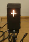 A lamp is mounted 50 cm away from the screen on the optical rail. A cross pattern is cut into the lamp cover.
The cross faces the screen. A lens can be moved along the rail to different
positions between the lamp and the screen.
A lamp is mounted 50 cm away from the screen on the optical rail. A cross pattern is cut into the lamp cover.
The cross faces the screen. A lens can be moved along the rail to different
positions between the lamp and the screen.Table 1
| screen-lamp distance |
measured xo |
measured xi |
calculated focal length: f = xoxi/(xo + xi) |
inverted? |
|---|---|---|---|---|
| 50 cm (1) | ||||
| 50 cm (2) |
For the measurements of experiment 1 and 2 answer the following questions.
Simulation 1:
Open the "Lenses" simulation.
You can determine the effective focal length of a bi-convex and two plano-convex lenses. The object is a parallel beam (representing a point source at infinity). You can vary the aperture size by varying the beam radius. Use the mouse to move the lens and the screen along an optical rail and to zoom and rotate the view. The major unit of the scale on the track is cm. For large apertures, look for spherical aberrations and observe coma and astigmatism as you rotate the lens. For some lenses coma is the dominant aberration, while for others it is astigmatism.
(a) Choose a beam radius of ~ 0.7 cm and a lens rotation of zero. In succession, choose lens # 1 - 4. These are not necessarily thin lenses. Determine the effective focal length of each lens by bringing the parallel laser beam to a focus on the screen. Varying the distance between the lens and screen until the best focus is achieved.
Fill in the table below.
Table 2
| Lens # | Lens | focal length |
|---|---|---|
| 1 | 1 | |
| 2 | 2-flat side facing beam | |
| 3 | 3-flat side facing beam | |
| 3 | 3-curved side facing beam |
Paste your table into your log.
Does it matter which side of lens 3 is facing the beam?
(b) Observe coma.
Choose lens 2 and put the screen in its focal plane. Rotate the lens by
~ 30 degrees in either direction.
Simulation 2:
Open the "Images" simulation.
You can also determine the effective focal length of a bi-convex and two plano-convex lenses by using a lamp with markings as the object. Use the mouse to move the lamp, lens, and the screen along an optical rail and to zoom and rotate the view. The major unit of the scale on the track is cm. For large apertures, look for spherical aberrations and observe coma and astigmatism as you rotate the lens.
(a) Choose lens 2, an aperture size of 0.7 cm and a lens rotation of 0. Place the lamp 9 cm in front of the lens and move the screen until you find the sharpest image. Measure the image distances. Calculate the focal length of lens 2 from f = xoxi/(xo + xi).
Observation 1
 A
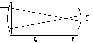
simple Keplerian telescope with a magnifying power of ~3.1 is mounted on the
optical rail.
It uses 12.5 cm focal length lens for the objective and the 4 cm focal length lens for the eyepiece.
The center to center distance between the lenses be ~16.5 cm.
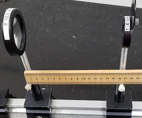
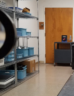
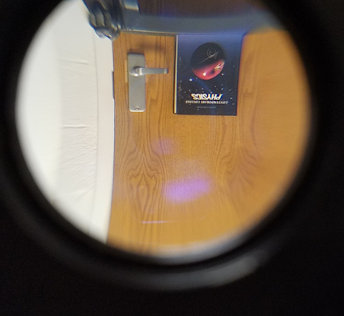
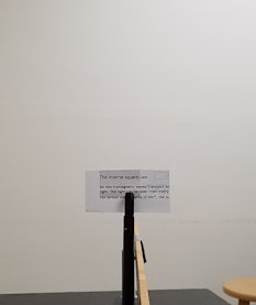
The telescope is pointed at a book sitting standing on a cart near a door across the room. The camera looks through the eyepiece and takes a picture. The lens of the camera produces a real image at the location of the camera sensor. The picture on the left is taken with the camera in the same position and the telescope moved to the side.
Observation 2
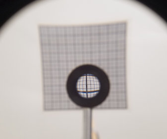
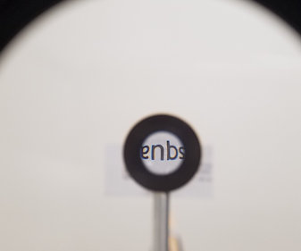
A (very poorly designed) simple compound microscope with a tube length g of 16 cm, an objective with focal length fo = 6 cm, and an eyepiece with focal length 12.5 cm is mounted on an optical rail. 16 cm is the most common tube length for laboratory microscopes. The center to center distance between the lenses be 34.5 cm. The target is placed ~8.5 cm in front of the objective. The magnifying power of this microscope, when the human eye is used as the detector, is MP = -(g/fo)(25 cm/fe) ~ 5.3. Here the camera is used as a detector. The camera lens is positioned close to the eyepiece and moved and forms a reasonably sharp image of the object on the camera sensor.
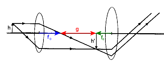
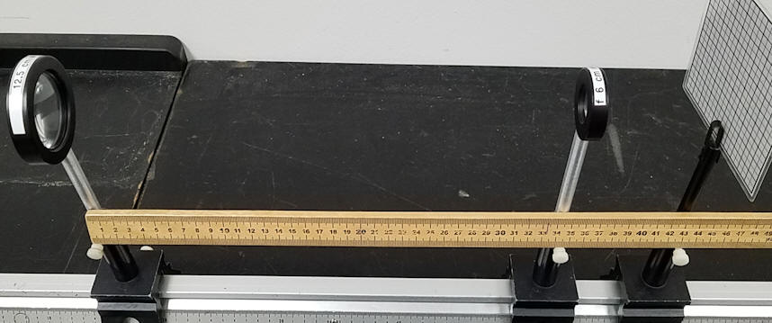
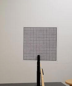
Below you see the image of the target produced by the camera lens. The eyepiece lens is large, there is no actual tube, and the camera lens has a wide acceptance angle, so the camera can "look around" the objective. The picture on the left is taken with the camera in the same position and the microscope moved to the side.
Convert your log into a lab report. See the grading scheme for all lab reports.
Name:
E-mail address:
Laboratory 8 Report
Save your Word document (your name_lab8.docx), go to Canvas, Assignments, Lab 8, and submit your document.